Sub-Assembly - 11 -
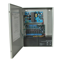
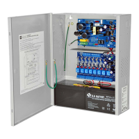
Installation Instructions for Power Supply/Chargers (BC300 Enclosure):
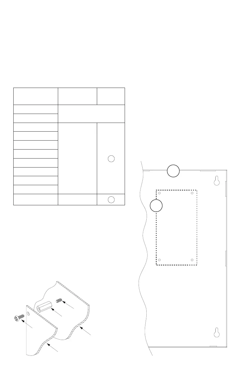
1. Fasten standoffs onto metal pems configuration (A) of enclosure (Fig. 10, pg. 11).
2. Position Sub-assembly module over standoffs and secure module into enclosure with four (4) pan head
screws supplied (Fig. 10a, pg. 11).
3. Refer to the corresponding Power Supply/Charger Installation Guides:
AL300ULX Series, AL400ULX Series, AL600ULX Series, eFlow3N Series, eFlow4N Series,
eFlow6N Series, eFlow102N Series, eFlow104N Series and individual Sub-Assembly Installation Guides
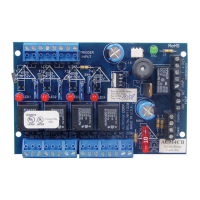
for the following models: ACM4(CB), LINQ2, LINQ8PD(CB), MOM5, PD4UL(CB), PD8UL(CB),
PD16W(CB), PDS8(CB), VR6 for further installation instructions (Pgs. 20-21).
Sub-Assembly Position Chart for the Following Models:
AL300ULX, AL300ULXR, AL400ULX, AL400ULXR, AL600ULX, AL600ULXR,
eFlow3N, eFlow4N, eFlow6N, eFlow102N, eFlow104N.
Sub-Assembly
Module
Mounting
Position
Mounting
ACM8(CB)
Not Applicable
ACMS8(CB)
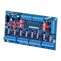
LINQ8PD(CB)
Right of Power
Supply
A
ACM4(CB)
MOM5
PD4UL(CB)
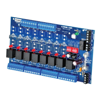
PD8UL(CB)
PD16W(CB)
PDS8(CB)
VR6
LINQ2* Top edge B
* LINQ2 can be installed when utilizing
eFlow power supply/charger boards.
A
B
Pem
Standoff
Sub Assembly
Enclosure
Pan Head
Screw
Fig. 10a
Fig. 10