EasyManua.ls Logo

Altronix AL400ULACM User Manual

Altronix AL400ULACM
12 pages
To Next Page IconTo Next Page
Page #1 background imageLoading...
Page #1 background image
ACM Series
Access Power Controllers
with Power Supplies
Installation Guide
Models Include:
AL400ULACM AL600ULACM
- 12VDC @ 4 amp - 12VDC or 24VDC @ 6 amp.
or 24VDC @ 3 amp - Fused Outputs
- Fused Outputs
AL1012ULACM AL1024ULACM
- 12VDC @ 10 amp. - 24VDC @ 10 amp.
- Fused Outputs - Fused Outputs
For a red enclosure add an “R” suffix to the part # e.g. AL1024ULACMR
Rev. 102512
Available from A1 Security Cameras
www.a1securitycameras.com email:sales@a1securitycameras.com
Question and Answer IconNeed help?

Do you have a question about the Altronix AL400ULACM and is the answer not in the manual?

Altronix AL400ULACM Specifications

General IconGeneral
Output Current4A
Continuous Supply Current4A
Battery BackupYes
Capacity7Ah
SupervisionYes
Fire Alarm DisconnectYes
Overvoltage ProtectionYes
HousingMetal
MountingWall mount
Input50/60Hz
Output Voltage12VDC or 24VDC
Operating Temperature0°C to 49°C
CertificationsUL Listed
Input Voltage115VAC

Summary

ACM Series Overview and Specifications

Configuration Reference Chart

Comparative data for ACM models' features and ratings.

System Specifications

Details power inputs, trigger options, outputs, and FACP disconnect features.

Installation and Configuration

Mounting, Voltage, and AC Connection

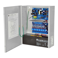
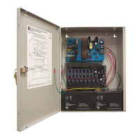
Steps for physical mounting, setting output voltage, and connecting AC power.

Switched and Auxiliary Output Setup

How to configure switched and unswitched auxiliary power outputs.

Installation and Configuration (Continued)

Advanced Output, Input, and FACP Features

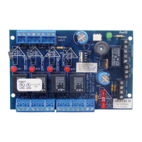
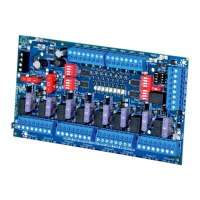
Configures form "C" outputs, input triggers, and FACP interface options.

Battery and Supervision Configuration

Connects batteries, AC/battery supervision, and dual power supplies.

Maintenance and Testing

Output Voltage and Battery Health Checks

Procedures for testing output voltage and battery status.

Visual Guides and Diagnostics

Typical Application Diagram

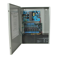
Illustrates common system wiring and connections.

LED Status Indicators

Explains the meaning of power supply and controller LEDs for diagnostics.

Power Supply Board Wiring

Terminal Identification

Power Supply Board Terminals

Lists and defines terminals on the power supply board.

ACM8 Controller Terminals

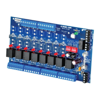
Lists and defines terminals on the ACM8 controller.

FACP Interface Terminal Functions

Details FACP input and output terminal functions.

Wiring Hook-Up Diagrams

Dual Isolated Power Supply Hook-up

Diagram for connecting two separate power supplies.

FACP Trigger Input Wiring

Diagrams for various FACP trigger input configurations.

AL1024ULACM Battery Size Calculation Worksheet

Enclosure Dimensions Diagram

Related product manuals