Sub-Assembly - 9 -
Installation Instructions for Maximal (BC800 Enclosure):
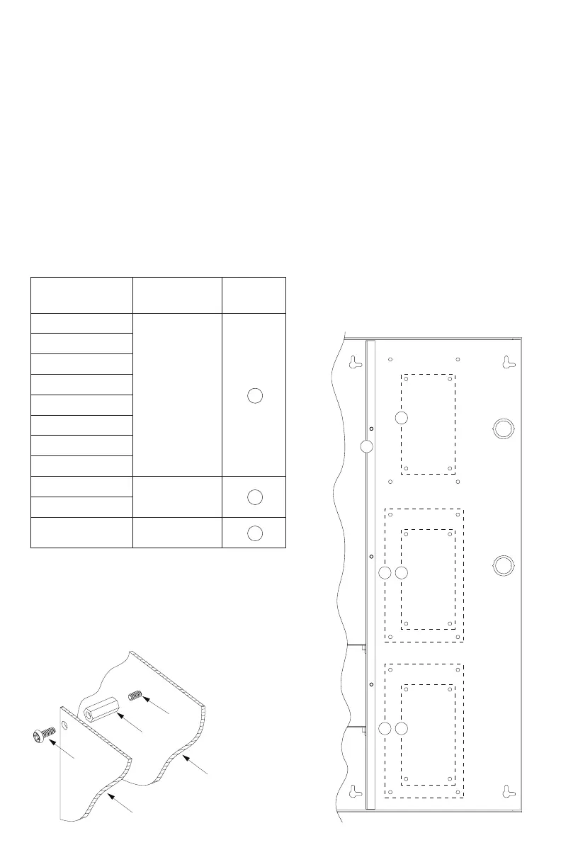
1. Fasten standoffs onto metal pems configuration (A) or configuration (B) of enclosure depending on the
sub-assembly module (Fig. 8, pg. 9). ACM8(CB) modules can only be installed in the middle or bottom
mounting positions of the Maximal enclosure.
2. Position sub-assembly module over corresponding standoffs and secure module into enclosure with four (4)
pan head screws supplied (Fig. 8a, pg. 9).
3. Refer to the Maximal Access Power Controllers Installation Guides for: Maximal 3/5/7,
Maximal 3D/5D/7D, Maximal 3F/5F/7F, Maximal 3FD/5FDFD, Maximal 11/33/55/75/77,
Maximal 11D/33D/55D/75D/77D, Maximal 11F/33F/55F/75F/77F,
Maximal 11FD/33FD/55FD/75FD/77FD (Pgs. 20-21).
Refer to the Maximal Expandable Power Systems Installation Guides for:
Maximal 11E/13E/33E/35E/37E/55E/75E/77E,
Maximal 11FE/FE/33FE/35FE/37FE/55FE/75FE/77FE (Pg. 22),
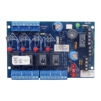
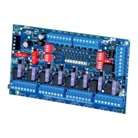
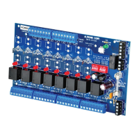
and individual Sub-Assembly Installation Guides for the following models: LINQ8PD(CB), ACM4(CB),
LINQ2, MOM5, PD4UL(CB), PD8UL(CB), PD16W(CB), PDS8(CB), ACM8(CB), ACMS8(CB), VR6
for further installation instructions.
Sub-Assembly Position Chart for the Following Models:
Maximal Access Power Controller and Maximal Expandable Power Systems (refer to instruction #3 above).
Sub-Assembly
Module
Mounting
Position
Mounting
LINQ8PD(CB)
Top, Middle
& Bottom
A
ACM4(CB)
MOM5
PD4UL(CB)
PD8UL(CB)
PD16W(CB)
PDS8(CB)
VR6
ACM8(CB)
Middle & Bottom B
ACMS8(CB)
LINQ2* Edge of Divider C
* LINQ2 can be installed when utilizing
eFlow power supply/charger boards.
Top
Middle
Bottom
A
B
C
A
B A
Pem
Standoff
Sub Assembly
Enclosure
Pan Head
Screw
Fig. 8a
Fig. 8