- 2 - AL175UL
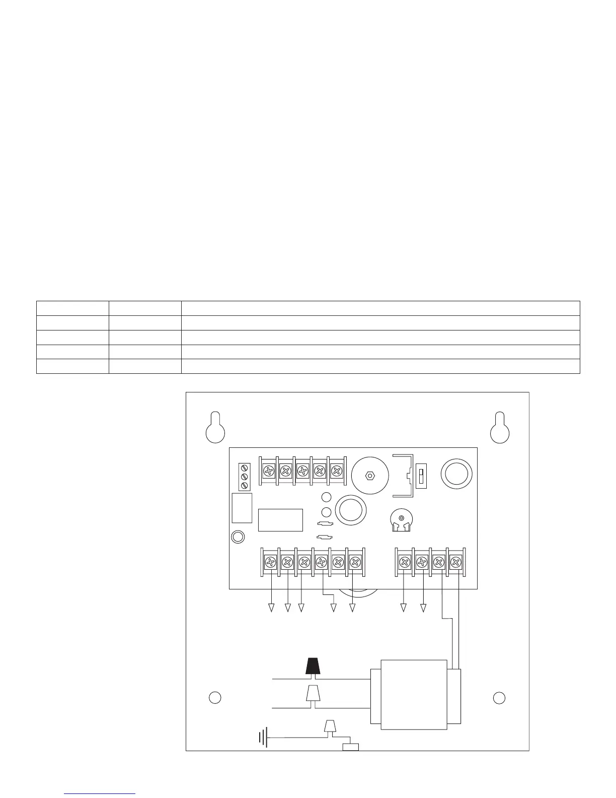
115VAC input
60 Hz,
0.6 amp
Green Lead
(ground)
Black
Lead
White
Lead
Stand-by
Battery
(optional)
Constant output
(Not affected
by trigger)
XFMR
Switched
DC output
(trigger control)
NC
DC
AC
C TRG1 TRG2
ACAC+ BAT --
COM -- AUX --LOCK + AUX +FACPSTRIKE +
SW1 ON - 24V
OFF - 12V
SW1
VR1
NO
NC CNO
AC FAIL
ON
Fig. 1
5. Connect battery to the terminals marked [+ BAT -] (battery leads included). Use two (2) 12VDC batteries connected
in series for 24VDC operation.
Note: For Access Control applications batteries are optional. When batteries are not used, a loss of AC will result in
the loss of output voltage. When the use of stand-by batteries are desired, they must be lead acid or gel type.
6. Connect appropriate signaling notification devices to AC Fail supervisory relay outputs marked [NC, NO, C].
Note: To meet UL requirements, AC Supervisory outputs must be connected to the zone of Alarm Control Panel or
to visual AC trouble indicator.
7. For Access Control Device & Fire Alarm Interface connections refer to desired Application Diagrams (pg. 4)
and (Terminal Identification Chart, pg. 3).
Maintenance:
Unit should be tested at least once a year for the proper operation as follows:
Output Voltage Test: Under normal load conditions the DC output voltage should be checked for proper voltage level
(see Power Supply Output Specifications Chart).
Battery Test: Under normal load conditions check that the battery is fully charged, check specified voltage both
at the battery terminal and at the board terminals marked [- BAT +] to ensure that there is no break in the battery
connection wires.
Note: Maximum charging current under discharges is 400mA.
Note: Expected battery life is 5 years; however, it is recommended changing batteries in 4 years or less if needed.
LED Diagnostics:
Red (DC) Green (AC) Power Supply Status
ON ON Normal function.
ON OFF Battery backup is powering output.
OFF ON No DC output.
OFF OFF Loss of AC. Discharged or missing stand-by battery. No DC output.

 Loading...