AL802ULADA - 5 -
Class A, Class B SW1 & SW2 Settings:
• For all Class B hookups SW1 and SW2 on the AL800LGK logic board must be turned OFF.
For all Class A hookups SW1 and SW2 on the AL800LGK logic board must be turned ON.
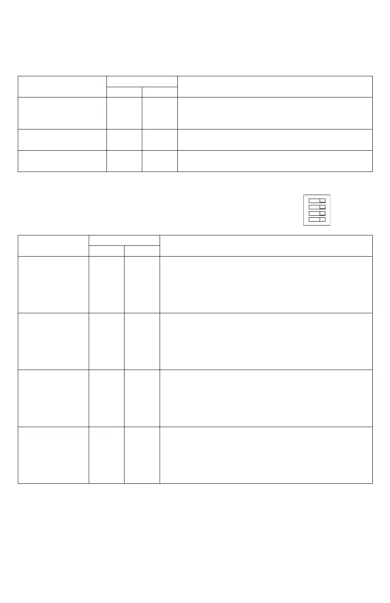
Output Programming Selection Table:
Outputs must be programmed independently (OUT1 - OUT4)
Function
Switch Positions
Descriptions
ON OFF
Input to Output
Follower Mode
1 2, 3
Output follows signal it receives from the corresponding
input (i.e. FACP Sync module - maintains synchronization
of notification appliance circuit).
Temporal Code 3 Mode 3 1, 2
Enables Temporal Code 3 signal generation output.
This mode will accept a steady or a pulsing input.
Steady Mode 1, 2, 3
A steady output signal will be generated.
This mode will accept steady or pulsing input.
For the above modes DIP Switch 4 determines which Input controls the
corresponding output:
Switch 4 in the ON position causes output(s) to be controlled by Input 1.
Switch 4 in the OFF position causes output(s) to be controlled by Input 2.
Sync Mode Selection Table:
Function
Switch Positions
Descriptions
ON OFF
Amseco
Sync Mode*
1, 3,
4
2
This mode is designed to work with the Amseco series of horns,
strobes, and horn/strobes to provide a means of synchronizing the
Temporal-coded horns, synchronizing the flash timing of the strobe,
and allowing audible notification appliances (horns) and visual
notification appliances (strobes) to be silenced/ deactivated at the
same time.
Gentex
®
Sync Mode*
Gentex is a registered
trademark of
Gentex Corporation.
1, 2,
3, 4
This mode is designed to work with the Gentex
®
series of horns,
strobes, and horn/strobes to provide a means of synchronizing
the Temporal-coded horns, synchronizing the flash timing of the
strobe, and allowing audible notification appliances (horns) and
visual notification appliances (strobes) to be silenced/ deactivated
at the same time.
System Sensor
®
Sync Mode*
System Sensor is a
registered trademark of
Honeywell.
1, 2, 4 3
This mode is designed to work with the System Sensor
®
series of
horns, strobes, and horn/strobes to provide a means of synchroniz-
ing the Temporal-coded horns, synchronizing the one-second flash
timing of the strobe, and allowing audible notification appliances
(horns) and visual notification appliances (strobes) to be silenced/
deactivated at the same time.
CooperWheelock
®
Sync Mode*
CooperWheelock is a
registered trademark of
Cooper Wheelock.
2, 3, 4 1
This mode is designed to work with the CooperWheelock series of
horns, strobes, and horn/strobes to provide a means of synchronizing
the Temporal-coded horns, synchronizing the one-second flash timing
of the strobe, and allowing audible notification appliances (horns)
and visual notification appliances (strobes) to be silenced/ deacti-
vated at the same time.
*NOTE: The AL802ULADA will only synchronize horns, horn/strobes and strobes that contain synchronization
capability. The same synchronization mode must be selected for all outputs
NOTE: It is required to control visual notification appliances (strobes) via Input 1 (IN1) and audible
notification appliances (horns) via Input 2 (IN2). This allows audible notification appliances (horns) and
visual notification appliances (strobes) to be silenced/ deactivated at same time.
AL800LGK9E Board
Output DIP Switches
INPUT SELECT
TEMPORAL
STROBE SYNC
IN>OUT SYNC