AL802ULADA - 9 -
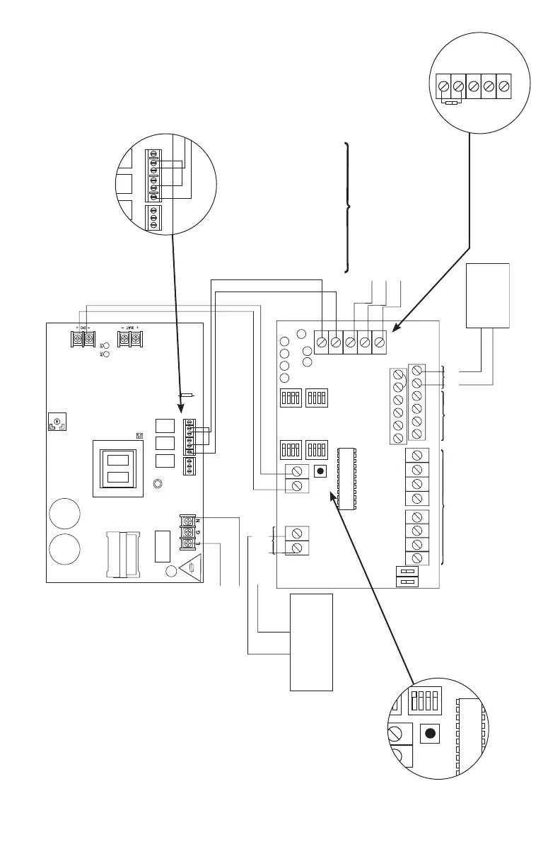
Hookup Diagram:
These circuits are used to
monitor AC and Bat Fail and
will cause a simultaneous trouble
condition to the FACP's IN1 and IN2
Digital Communicator or
Local Annunciator Dry output Contact
(Form "C" contacts).
Connection to triggering devices must be
made within 20 ft. of distance and using
conduit for wiring.
SW1
– DC +
SW2
+ OUT1 –
OUT1 OUT2 OUT3 OUT4
INP1 INP2
FAULT
NC CNOC "FAULT" NC
OUT1 OUT3
OUT2 OUT4
INPUT SELECT
TEMPORAL
STROBE SYNC
IN > OUT SYNC
IN1+
IN1–
IN2–
IN2+
C "DRY1" NC
RET1+
RET1–
RET2–
RET2+
C "DRY2" NC
+ OUT2 –
+ OUT3 –
+ OUT4 –
INPUT SELECT
TEMPORAL
STROBE SYNC
IN > OUT SYNC
– AUX +
UPPER TERMINALS
LOWER TERMINALS
Addressable
Control Module
Trigger Output
line
Input
Fuse
neutral
Use separate knockout.
Keep 0.25" spacing from
non power-limited wiring
Supervised Power-Limited Outputs
2.5A per output in alarm
Total = 8A
Supervised
power-limited
Inputs
Non-Supervised Class E
RESET
NC C NO
NC C NO NC C NO
AC Local
AC DELAY
BAT FAIL AC FAIL
AC LED
VR1
ON
1
ON
1
Compatible Special
Application Devices.
See Compatibility List
Unswitched 120VAC
power mains (non power-limited)
Non-Supervised Class E
Non-Supervised Class E
5A 250V
Fig. 2
These circuits are used to
monitor AC and Bat Fail and
will cause a simultaneous trouble
condition to the FACP's IN1 and IN2
Digital Communicator or
Local Annunciator Dry output Contact
(Form "C" contacts).
Connection to triggering devices must be
made within 20 ft. of distance and using
conduit for wiring.
SW1
– DC +
SW2
+ OUT1 –
OUT1 OUT2 OUT3 OUT4
INP1 INP2
FAULT
NC CNOC "FAULT" NC
OUT1 OUT3
OUT2 OUT4
INPUT SELECT
TEMPORAL
STROBE SYNC
IN > OUT SYNC
IN1+
IN1–
IN2–
IN2+
C "DRY1" NC
RET1+
RET1–
RET2–
RET2+
C "DRY2" NC
+ OUT2 –
+ OUT3 –
+ OUT4 –
INPUT SELECT
TEMPORAL
STROBE SYNC
IN > OUT SYNC
– AUX +
UPPER TERMINALS
LOWER TERMINALS
Addressable
Control Module
Trigger Output
line
Input
Fuse
neutral
Use separate knockout.
Keep 0.25" spacing from
non power-limited wiring
Supervised Power-Limited Outputs
2.5A per output in alarm
Total = 8A
Supervised
power-limited
Inputs
Non-Supervised Class E
RESET
NC C NO
NC C NO NC C NO
AC Local
AC DELAY
BAT FAIL AC FAIL
AC LED
VR1
ON
1
ON
1
Compatible Special
Application Devices.
See Compatibility List
Unswitched 120VAC
power mains (non power-limited)
Non-Supervised Class E
Non-Supervised Class E
5A 250V
Fig. 2b
Fig. 2a
Fig. 2c
Trouble Memory
Reset Button
Common trouble
Input/Output
These circuits are used to
monitor AC and Bat Fail and
will cause a simultaneous trouble
condition to the FACP's IN1 and IN2
Digital Communicator or
Local Annunciator Dry output Contact
(Form "C" contacts).
Connection to triggering devices must be
made within 20 ft. of distance and using
conduit for wiring.
SW1
– DC +
SW2
+ OUT1 –
OUT1 OUT2 OUT3 OUT4
INP1 INP2
FAULT
NC CNOC "FAULT" NC
OUT1 OUT3
OUT2 OUT4
INPUT SELECT
TEMPORAL
STROBE SYNC
IN > OUT SYNC
IN1+
IN1–
IN2–
IN2+
C "DRY1" NC
RET1+
RET1–
RET2–
RET2+
C "DRY2" NC
+ OUT2 –
+ OUT3 –
+ OUT4 –
INPUT SELECT
TEMPORAL
STROBE SYNC
IN > OUT SYNC
– AUX +
UPPER TERMINALS
LOWER TERMINALS
Addressable
Control Module
Trigger Output
line
Input
Fuse
neutral
Use separate knockout.
Keep 0.25" spacing from
non power-limited wiring
Supervised Power-Limited Outputs
2.5A per output in alarm
Total = 8A
Supervised
power-limited
Inputs
Non-Supervised Class E
RESET
NC C NO
NC C NO NC C NO
AC Local
AC DELAY
BAT FAIL AC FAIL
AC LED
VR1
ON
1
ON
1
Compatible Special
Application Devices.
See Compatibility List
Unswitched 120VAC
power mains (non power-limited)
Non-Supervised Class E
Non-Supervised Class E
5A 250V