Trove1PH1 / TC1 / Trove2PH2 / TCV2 - 3 -
TC1: Configuration of Altronix Power Supply, Sub-Assemblies and Openpath Modules
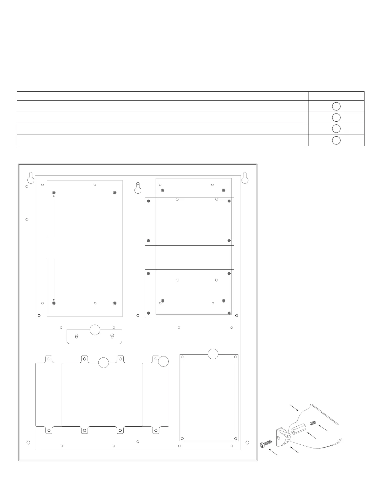
1. Push 5/16” pan head screws (provided) through the wholes in the backplane that match the pattern for Altronix Power Supply/
Charger and/or sub-assemblies from the backside of backplane. Screw spacers onto screws.
Fasten metal spacers in the correct locations to provide proper grounding, see below (Fig. 2, pg. 3).
2. Mount boards to spacers utilizing 5/16” pan head screws (provided) (Fig. 2a, pg. 3).
3. Mount appropriate Openpath boards into the correct positions by postioning pre-mounted spacers over appropriate holes on the
backplane and depressing down on board to secure spacer to the backplane (Fig. 2, pg. 3).
4. Fasten TC1 backplane to Trove1 enclosure utilizing pan head screws (provided).
Access Controller Position Chart for the Following Openpath Modules:
Openpath Mounting Position
OP-ACC A
OP-EX-4E B
OP-EX-8E C
OP-16EM D
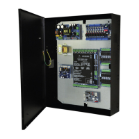
Fig. 2 - Trove1PH1/TC1 Configurations
Metal
Spacer
Placement
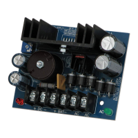
Altronix
Power
Supply
Altronix
Sub-Assemblies
D
C
B
A
Spacer
Altronix
Sub-Assembly
Backplane
Pan Head
Screw
Pan Head Screw
(through backplane)
Fig. 2a