IPB-5000B
8. External Interface
8-4
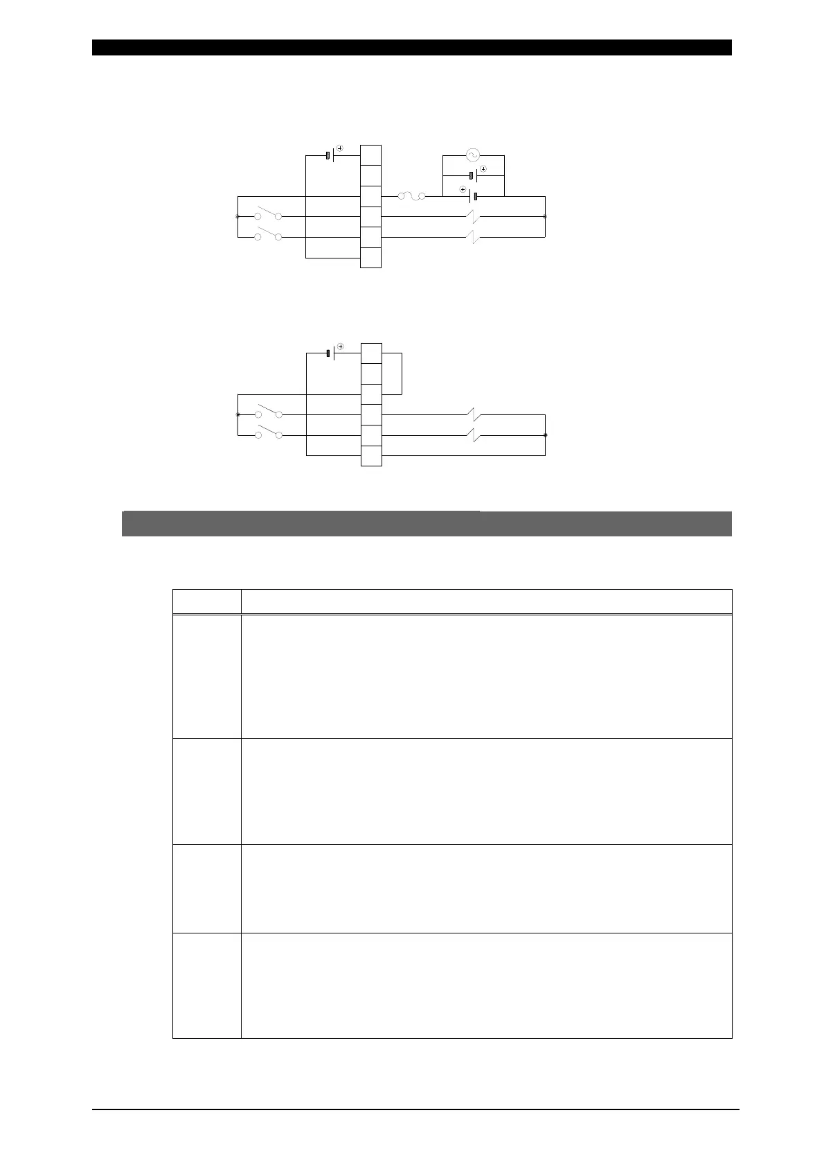
When solenoid valves are activated by the use of an external power supply
When solenoid valves are activated by the use of an internal power supply
(2) External Input/Output Signals
The contact input method is described as follows:
Pin No. Description
1
24V DC Output Terminal.
When contacts or NPN transistor (sink type) on PLC is used as an
input signal (for start or selecting Schedule, etc.), connect Pin 1 to Pin
2.
Note: Do not use Pin 1 other than for connecting to Pin 2 and Pin 3 or
connecting to Pin 31 to activate a solenoid valve. If so, it may
result in a trouble.
2
When contacts or NPN transistor (sink type) on PLC is used as an
input signal (for start or selecting Schedule, etc.), connect Pin 2 to Pin
1.
When PNP transistor (source type) on PLC is used as an input signal
(for start or selecting Schedule, etc.), connect Pin 2 to COM Terminal
on PLC.
3
Normally, connect Pin 3 to Pin 1.
When opening Pin 3, a trouble display “Operation Stop” comes out and
the operation stops.
When the sequence is required to stop on the way while employing the
start in a self-sustaining manner, open this Pin.
4
1ST STAGE Input Terminal.
Closing of this Pin makes SOL1 Terminal of Pin 32 close.
As the current-supplying sequence does not start, the adjustment or
check of a squeeze location can be done. When closing 2ND STAGE
Terminal at this location, the weld at the optimum squeeze location can
be obtained.
34
33
32
31
1
24VDC
…
SOL POWER
SOL 1
SOL 2
SOL COM
120VAC
24VDC
34
33
32
31
1
24VDC
…
SOL POWER
SOL 1
SOL 2
INT.24V
SOL COM
 Loading...


