CHAPTER 3: USING PROGRAMMING FUNCTIONS
IS-300CA INVERTER POWER SUPPLY
990-418 3-5
c. WELD (1, 2, 3)
Set the length of time to allow welding current to flow. As units of time, ms and CYC may be selected.
Either unit can be selected via the MODE SELECT screen.
UP (1, 2, 3)
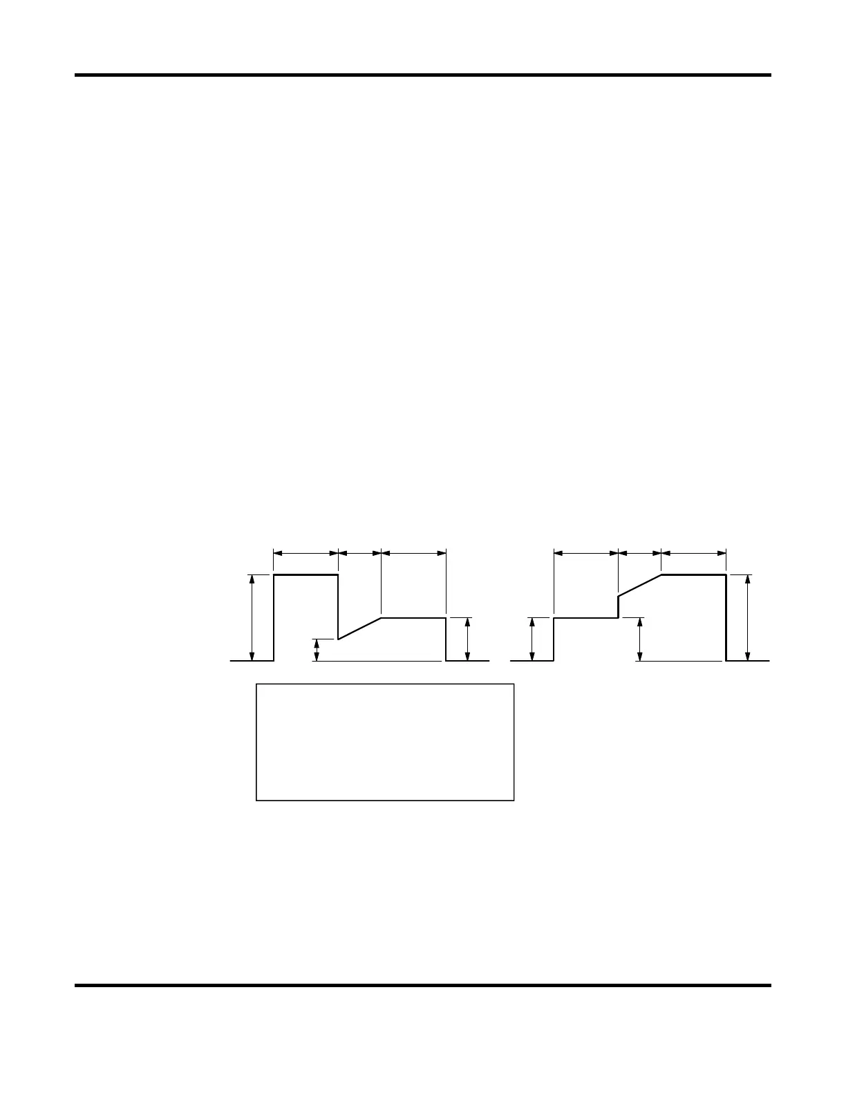
Set the upslope time (to increase the welding current gradually).
DOWN (1, 2, 3)
Set the downslope time (to decrease the welding current gradually).
NOTE: Upslope / Downslope waveform when COOL (cooling time) is set to 0. The welding
current normally increases from the UF set value to the HEAT set value and decreases from the
HEAT set value to the UF set value, but E-10 (Schedule setting error) will occur when the Power
Supply starts with the following setting.
When the control methods for the previous and subsequent stages in the multi-stage welding are
changed. The control method for the previous stage is different from that for the subsequent
stage.
When the upslope time is set for the subsequent stage in the multi-stage welding, the upslope
time is set for the subsequent stage, and the HEAT setting of D and the UF HEAT setting of E are
different.
E
F
CBA
D
D
A
F
CB
E
When the downslope time is set for the previous stage in the multi-stage welding, the downslope
time is set for the previous stage, and the DL HEAT setting of E and the HEAT setting of F are
different.
A: WELD1 time or WELD2 time
B: UP2 time or UP3 time
C: WELD2 time or WELD3 time
D: WELD1 HEAT or WELD2 HEAT
E: UF2 HEAT or UF3 HEAT
F: WELD2 HEAT or WELD3 HEAT
 Loading...