CHAPTER 3: USING PROGRAMMING FUNCTIONS
IS-300CA INVERTER POWER SUPPLY
990-418 3-11
a. SCHEDULE #
Select from #1 to #255 to set the SCHEDULE. Normally select #1 first, then select additional
schedules in sequential order.
b. PULSE LIMIT
When limiting the pulse width in Primary constant-current peak value control, set the limit for
each of WE1, WE2 and WE3.
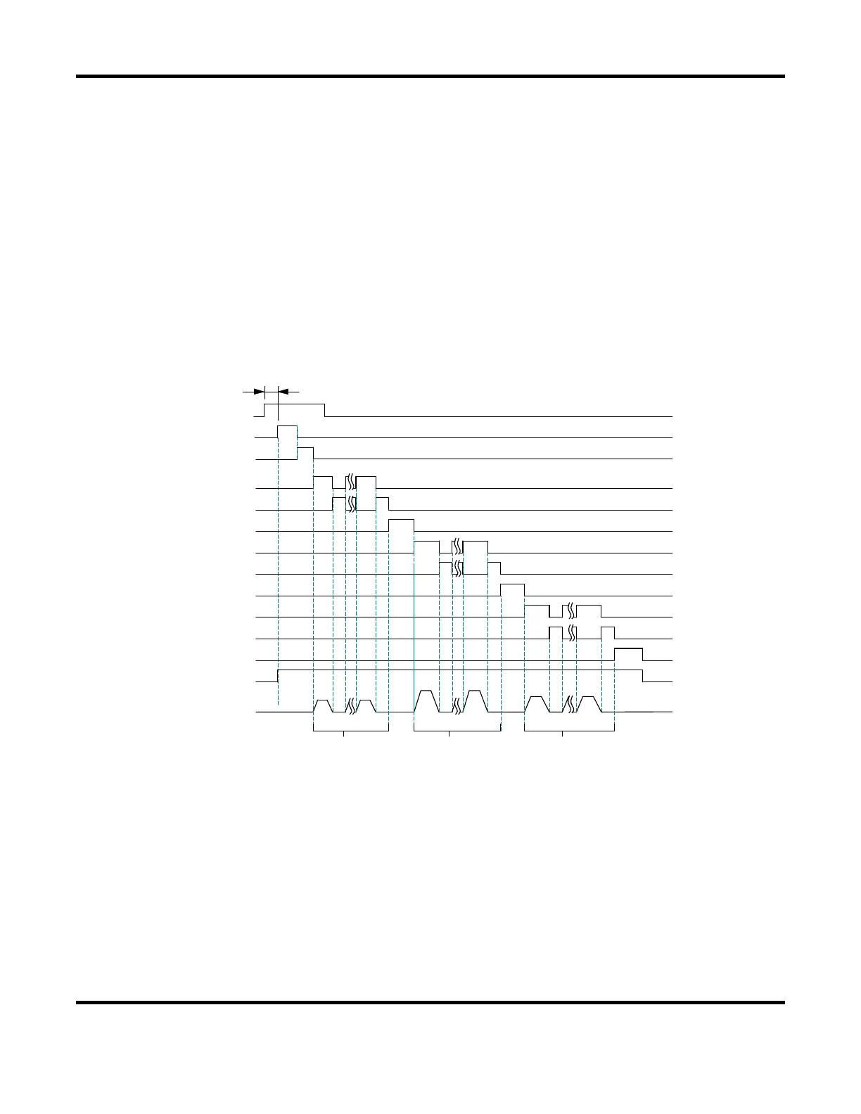
c. PULSATION / INTERVAL 1 to 3
Set the number of repetitions PULSATION (01 to 19) and the downtime (INT1 to 3) in WE1 to 3
(See the figure below); however, when the number of repetitions is set to 01, the downtime does
not work.
2ND
SQD
SQZ
A
A:DELAYSTARTSET
WELD1
COOL1
WELD2
COOL2
WELD3
INT 2
INT 1
HOLD
INT 3
HEAT1 HEAT1
HEAT2 HEAT2 HEAT3HEAT3
PU LSAT ION1
PULSAT ION 2
PU LSAT ION3
VALVE OUTPUT
ELD CURRENT
When performing a welding with the setting PULSATION to 02 or more and INT1 to 3 to 0,
set the control system to the primary constant-current effective value control or the primary
constant-current peak value control. If a welding is performed with the other controls, control
and monitored value may not function correctly.
When performing a welding with the setting PULSATION to 02 or more, only the last welding
data is displayed as the monitored value of
WELD2 after completion of sequence. In the
timing chart above, the data of the third time is displayed, see the MONITOR screen. If the
current gets out of the range of upper/lower limit judgment during repeated
PULSATION
operation, a caution signal is output after completion of welding (see the MONITOR SET
screen.)
 Loading...