CHAPTER 3: USING PROGRAMMING FUNCTIONS
IS-300CA INVERTER POWER SUPPLY
3-18 990-418
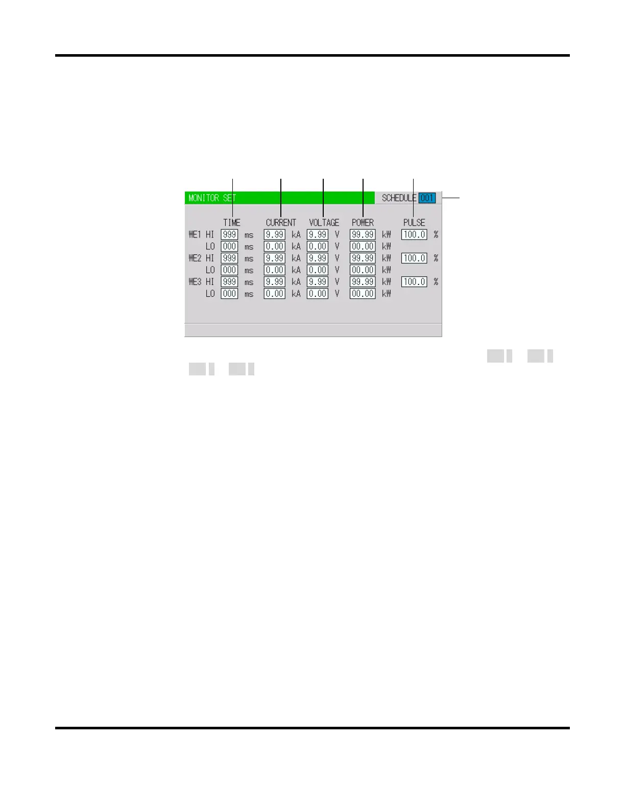
5. MONITOR SET Screen
Set the conditions for determining a good or bad weld, including values for welding current, upper
or lower limits for the secondary voltage, etc. If the monitored welding current, secondary voltage,
etc., do not meet the set conditions, a caution signal is output, and can be used to activate an alarm
buzzer, alarm lamp, or similar event.
(b) (c) (d) (e) (f)
(Note) The screen shows the settings for 10 kA or 5 kA range. In 20 kA CURRENT is 000.0 to 999.9 kA
and POWER is 000.0 to 999.9 kW.
a. SCHEDULE
Input the number of the SCHEDULE to monitor.
b. TIME
Set the upper limit (HI) and lower limit (LO) of the weld time for each of WE1, WE2 and WE3.
Use this function to monitor the weld time when it becomes unstable by the welding stop input.
c. CURRENT
Set the upper limit (
HI) and lower limit (LO) of the welding current for each of WE1, WE2 and
WE3.
d. VOLTAGE
Set the upper limit (
HI) and lower limit (LO) of the secondary voltage for each of WE1, WE2 and
WE3.
e. POWER
Set the upper limit (
HI) and lower limit (LO) of the electric power for each of WE1, WE2 and
WE3.
(a)
 Loading...