CHAPTER 3: USING PROGRAMMING FUNCTIONS
IS-300CA INVERTER POWER SUPPLY
990-418 3-19
f. PULSE
If the ratio of welding current pulse / pulse width in full wave mode exceeds the percentage set
in the PULSE HIGH, an ERROR signal is output. Pulse width is expressed assuming that the full
wave is 100%.
NOTE: Upper/Lower limit judgment value when STEPPER MODE is set to ON. The
upper/lower limit judgment value set here is for the current when a welding is performed, not for
the initial setting. Therefore, when STEPPER MODE is set to ON to perform step-up (step-
down) for the initial setting, the upper/lower limit judgment value is stepped up or down
automatically.
EXAMPLE: When the current is set to 2 kA, HI; 2.2 kA, LO; 1.8 kA. When the step becomes
150%,
H and L become as follows.
H: 2.2 x 1.5 = 3.3 kA
L: 1.8 x 1.5 = 2.7 kA
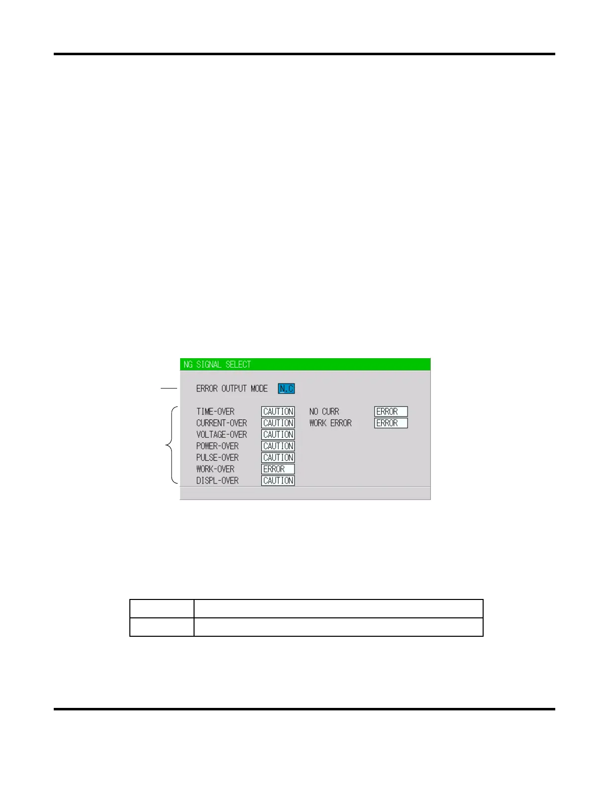
6. NG SIGNAL SELECT Screen
Sets the output mode and the signal for each item to output, ERROR or CAUTION, in an error
occurring.
NOTE: This screen shows initial settings.
a. ERROR OUTPUT MODE
Sets the output modes of
NG1 of the external output signals.
N.C.
(NORMAL CLOSE) Closed at normal / Open at error
N.O.
(NORMAL OPEN) Open at normal / Closed at error
NOTE: NG2 is N.O. only
(a)
(b)
 Loading...