CHAPTER 3: USING PROGRAMMING FUNCTIONS
IS-300CA INVERTER POWER SUPPLY
3-42 990-418
WELD STOP OFF T IME
Se t va lue
We ld ing s top
signal input
When the welding stop signal is input after WELD STOP OFF TIME
The welding is stopped when the welding stop signal is input.
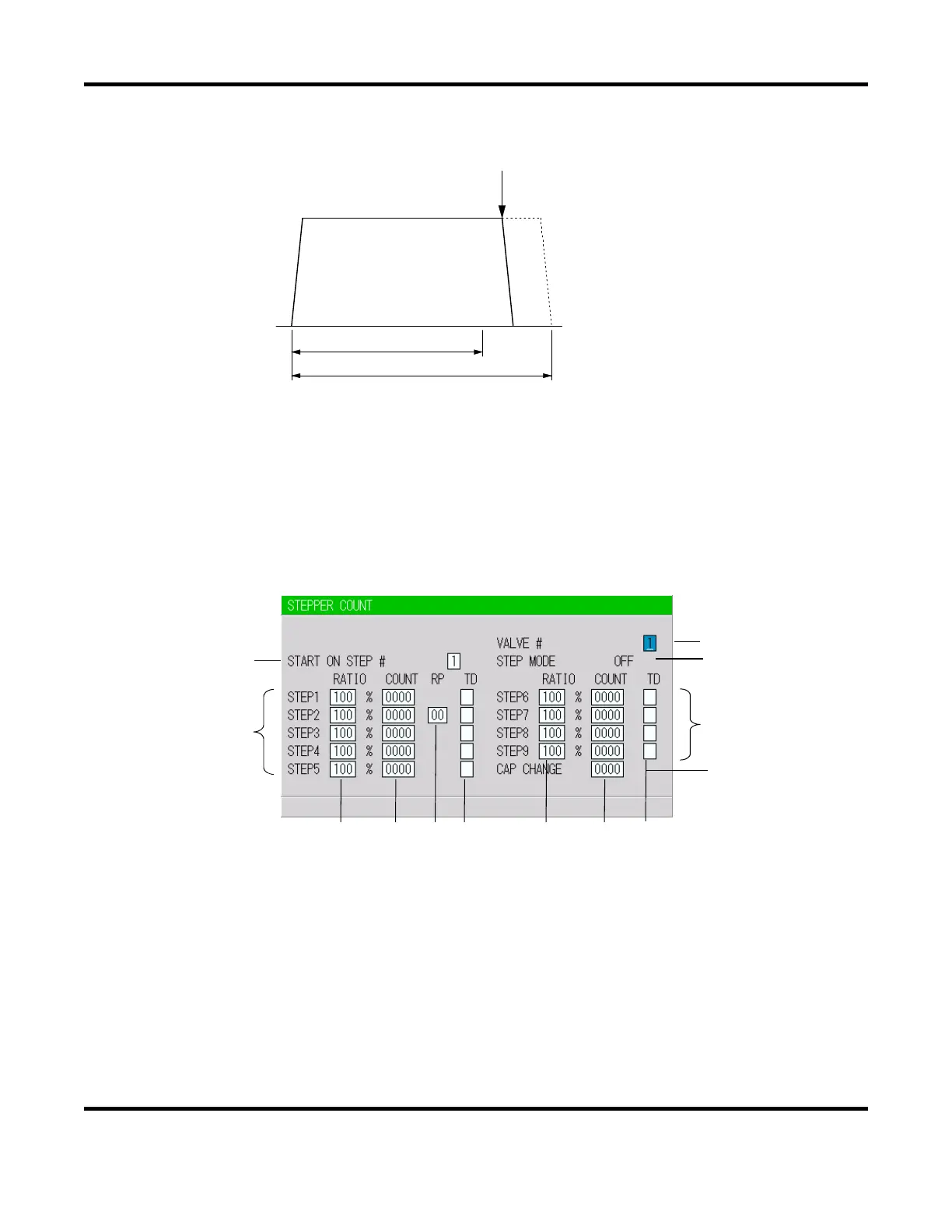
11. STEPPER COUNT Screen
The Power Supply can change the level of the welding current depending on the welding conditions.
The function to increase the welding current is called the “step-up” function, and that to decrease the
welding current is called the “step-down” function. Set the step-up or step-down timing based on
the number of welds. When the set number of welds is complete, the step end signal (STEP END)
is output.
a. START ON STEP #
The counting of welds starts from the STEP set here.
If, for example, you select START ON STEP #3 as shown above, welds will be counted from
the first weld in STEP3, even if welding for the first time. Further, the welding current will be
increased (or reduced) by the extent you have set this value for STEP3.
Set the desired STEP No. 1–9 for VALVE1 and VALVE2, or SOL 1 – 4, respectively,
depending on the valve mode selection.
(d) (e) (f) (g) (d) (e) (g)
(c)
(b)
(d)
(e)
(g)
(h)
(a)
(d)
(e)
(g)
 Loading...