EasyManua.ls Logo

Amana APG14 M Series User Manual

Amana APG14 M Series
40 pages
To Next Page IconTo Next Page
Page #1 background imageLoading...
Page #1 background image
Goodman Company, L.P.
IOG-3008H 5151 San Felipe, Suite 500, Houston, TX 77056
06/2019 www.goodmanmfg.com - or - www.amana-hac.com
© 2014-2019 Goodman Company, L.P.
Affix this manual and Users Information Manual adjacent to the unit.
INSTALLATION & OPERATING
INSTRUCTIONS for
A/GPG14 M SERIES W/R410A
SINGLE PACKAGE GAS-ELECTRIC
HEATING & COOLING UNIT
*NOTE: Please contact your distributor or our
website for the applicable Specification
Sheet or Technical Manual referred to in this
manual.
RECOGNIZE THIS SYMBOL AS A SAFETY PRECAUTION.
is a registered trademark of Maytag Corporation or its related companies and is used under license. All rights reserved.
O
NLY
PERSONNEL
THAT
HAVE
BEEN
TRAINED
TO
INSTALL
,
ADJUST
,
SERVICE
OR
REPAIR
(
HEREINAFTER
, “
SERVICE
”)
THE
EQUIPMENT
SPECIFIED
IN
THIS
MANUAL
SHOULD
SERVICE
THE
EQUIPMENT
. T
HE
MANUFACTURER
WILL
NOT
BE
RESPONSIBLE
FOR
ANY
INJURY
OR
PROPERTY
DAMAGE
ARISING
FROM
IMPROPER
SERVICE
OR
SERVICE
PROCEDURES
. I
F
YOU
SERVICE
THIS
UNIT
,
YOU
ASSUME
RESPONSIBILITY
FOR
ANY
INJURY
OR
PROPERTY
DAMAGE
WHICH
MAY
RESULT
. I
N
ADDITION
,
IN
JURISDICTIONS
THAT
REQUIRE
ONE
OR
MORE
LICENSES
TO
SERVICE
THE
EQUIPMENT
SPECIFIED
IN
THIS
MANUAL
,
ONLY
LICENSED
PERSONNEL
SHOULD
SERVICE
THE
EQUIPMENT
. I
MPROPER
INSTALLATION
,
ADJUSTMENT
,
SERVICING
OR
REPAIR
OF
THE
EQUIPMENT
SPECIFIED
IN
THIS
MANUAL
,
OR
ATTEMPTING
TO
INSTALL
,
ADJUST
,
SERVICE
OR
REPAIR
THE
EQUIPMENT
SPECIFIED
IN
THIS
MANUAL
WITHOUT
PROPER
TRAINING
MAY
RESULT
IN
PRODUCT
DAMAGE
,
PROPERTY
DAMAGE
,
PERSONAL
INJURY
OR
DEATH
.
This Forced Air Central Unit Design Complies With
Requirements Embodied in The American National
Standard / National Standard of Canada Shown Below.
ANSI Z21.47•CSA-2.3 Central Furnaces
These installation instructions cover the outdoor
installation of single package gas electric heating and
cooling units. See the Specification Sheet or Technical
Manual applicable to your model* for information
regarding accessories.
Cancer and Reproductive Harm -
www.P65Warnings.ca.gov
PROP 65 WARNING
FOR CALIFORNIA CONSUMERS
0140M00517-A

Table of Contents

Question and Answer IconNeed help?

Do you have a question about the Amana APG14 M Series and is the answer not in the manual?

Amana APG14 M Series Specifications

General IconGeneral
DehumidificationYes
Fan SpeedsMulti-Speed
RefrigerantR-410A
Compressor TypeScroll
SEER14.0
Power Supply230V
PhaseSingle

Summary

Installation and Operating Instructions

Safety Precautions

Highlights safety symbols and general precautions for safe operation and handling of the unit.

Prop 65 Warning

Provides a warning regarding chemicals known to cause cancer or reproductive harm in California.

Replacement Parts

Ordering Parts

Instructions on how to order replacement parts, including necessary unit information.

General Safety Instructions

Carbon Monoxide Poisoning Hazard

Safe Operation Procedures

Detailed steps to follow during operation to prevent carbon monoxide poisoning.

Fire and Explosion Hazards

General Information and Transportation

Transportation Damage

Procedures for inspecting and reporting any damage incurred during transportation of the unit.

Unit Locations and Installation Requirements

All Installations

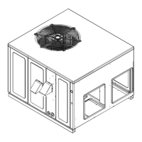
General guidelines for unit placement, ensuring proper function and safety across all installation types.

Ground Level Installations

Specific requirements for installing the unit on ground level, including base preparation.

Rooftop Installations

Key considerations for rooftop installations, focusing on structural integrity and safety.

Roof Curb and Rigging Procedures

Gas Piping

Overview of gas piping requirements and considerations for installation.

High Altitude Derate

Information on how altitude affects unit performance and required adjustments (U.S. only).

Piping and Gas Connections

Natural Gas Connection

Guidelines for connecting the unit to a natural gas supply, including pipe sizing and fittings.

Gas Piping Checks

Essential checks to perform on gas piping and connections to ensure safety and proper operation.

Propane Gas and Electrical Wiring

Tanks and Piping

Information regarding propane gas tank sizing, regulator settings, and piping requirements.

Thermostat Location

Recommendations for optimal placement of the thermostat for accurate temperature readings.

Thermostat Wiring and Control Operation

Single Stage Thermostat - Two-Stage Models

Instructions for configuring the unit to work with a single-stage thermostat on a two-stage system.

Electrical, Airflow, and Ductwork

Heat Anticipator Setting

Guidance on setting the heat anticipator for proper heating cycle control.

Airflow Conversion and Ductwork

Details on converting airflow direction and designing duct systems according to industry standards.

Filters, Venting, and Condensate Drain

Flue Hood Installation

Instructions for installing the exhaust flue hood and combustion air intake hood.

Normal Sequences of Operation - Heating

Normal Sequences of Operation - Cooling and Fan

Cooling Operation

Detailed description of the unit's cooling cycle, including compressor and fan operation.

Fan Only Operation

Explanation of how the unit operates in fan-only mode, controlled by the thermostat.

Startup, Adjustments, and Checks

Heating Startup Procedures

Procedures for initial startup and checking the heating system's operation.

Rollout Protection Control

Information on the rollout protection device and its function in preventing burner flame issues.

Secondary Limit Control and Pre-Operation Checks

Gas Supply Pressure Measurement

Procedure for measuring the inlet gas supply pressure to the unit.

Gas Supply Pressure Measurement Procedures

Gas Manifold Pressure and Flame Checks

Gas Input Check

Procedure for measuring the unit's gas input to ensure it matches specifications.

Main Burner Flame Check

Guidance on inspecting the main burner flame for proper appearance and stability.

Temperature and Static Pressure Checks

Blower Speed Adjustments

Instructions for adjusting blower speed to achieve proper temperature rise and airflow.

Unit Shutdown Procedure

Steps to follow for safely shutting down the unit for maintenance or other purposes.

Cooling Startup and Refrigerant Management

Compressor Protection Devices

Overview of the internal components designed to protect the compressor from abnormal conditions.

Cooling Refrigerant Charging

Detailed procedures for checking and adjusting refrigerant charge for optimal cooling performance.

Troubleshooting Overview

Ignition Control Error Codes

Explanation of diagnostic LED flash codes and their meanings for troubleshooting ignition issues.

Abnormal Operation - Heating

Common heating problems and their potential causes and solutions.

Abnormal Operation - Cooling and Limits

Pressure Switch Issues

Diagnosis and troubleshooting for pressure switch faults, including stuck open or closed conditions.

Thermal Protection and Flame Issues

Information on thermal limits, rollout protection, and flame sensor issues.

Maintenance Procedures

Cabinet Finish Maintenance

Recommendations for cleaning and maintaining the unit's exterior cabinet finish.

Flame Sensor and Flue Passages

Procedures for cleaning the flame sensor and flue passages for optimal performance.

Burner Maintenance and Parts

Cleaning Burners

Step-by-step instructions for cleaning the unit's burners.

Accessories and Functional Parts

List and description of available accessories and functional parts for the unit.

Ignition Control Diagnostics and Timing Charts

Heating Timing Chart

Visual representation of the timing sequence for various components during the heating cycle.

Cooling Timing Chart

Visual representation of the timing sequence for various components during the cooling cycle.

Two-Stage Ignition Control Diagnostics

Two-Stage Heating Timing Chart

Timing chart illustrating component operation for two-stage heating cycles.

Two-Stage Cooling Timing Chart

Timing chart illustrating component operation for two-stage cooling cycles.

Appendix: Unit Dimensions

Wiring Diagrams

Wiring Diagram and Status Codes

Installer/Serviceman Status Light Codes

Guide to interpreting status light codes on the control board for diagnosing operational issues.

Wiring Diagrams (Model Specific)

Wiring Diagram and Component Legend

Installer/Serviceman Status Light Codes

Reference for status light codes used by installers and servicers to diagnose unit faults.

Wiring Diagrams (Model Specific)

Wiring Diagram and Diagnostic Charts

Diagnostic LED Charts

Charts explaining diagnostic LED signals for troubleshooting, including error codes and their meanings.

Minimum Clearances and Filter Sizes

Recommended Filter Sizes

Table providing recommended filter sizes based on the unit's capacity and configuration.

Homeowner Maintenance Recommendations

Replace or Clean Filter

Instructions for checking, cleaning, and replacing air filters to maintain system efficiency.

Motor Bearings and Compressor

Information regarding the lubrication requirements for the unit's motors and compressor.

Before Calling Your Servicer

Essential checks a homeowner should perform before contacting a service technician for assistance.

Start-up Checklist

Start-up Checklist - Measurements

Customer Feedback and Product Registration

Related product manuals