Component Testing Procedures
!
WARNING
To avoid risk of electrical shock, personal injury or death; disconnect power to oven and discharge capacitor
before servicing, unless testing requires power.
RS2240003 Rev. 0 14
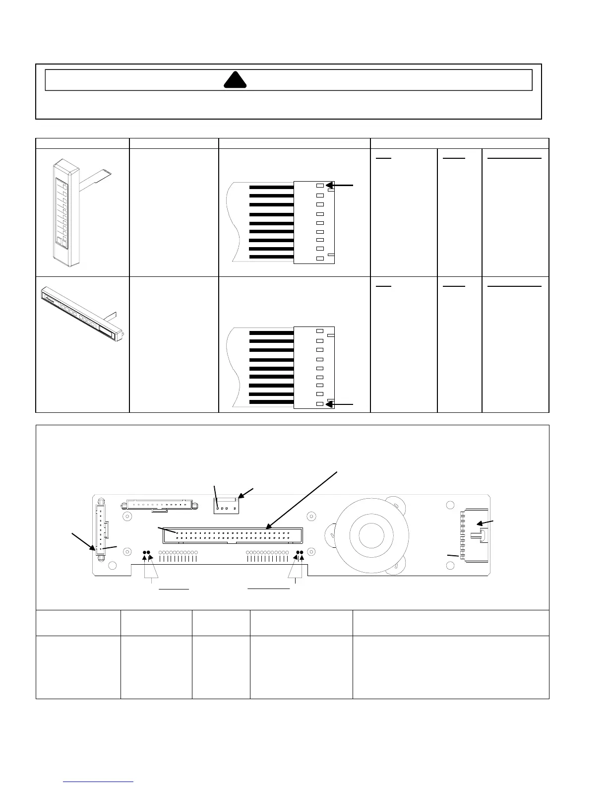
Illustration Component Test Results
Side touch panel
Continuity is indicated as 100 Ω and
below.
Pad
1
2
3
4
5
6
7
8
9
0
Start
Stop/Reset
Trace
3&5
3&6
3&7
3&8
3&9
4&5
4&6
4&7
4&8
4&9
5&6
6&9
Measurement
Continuity
Continuity
Continuity
Continuity
Continuity
Continuity
Continuity
Continuity
Continuity
Continuity
Continuity
Continuity
Top touch panel Removal of touch panel is required to
perform test.
Continuity is indicated as 100 Ω and
below.
Pad
Time Entry
Power Level
Stage
Program Save
Quantity
Menu
Hidden Pad
Trace
5&7
5&8
5&9
6&7
6&8
7&9
8&9
Measurement
Continuity
Continuity
Continuity
Continuity
Continuity
Continuity
Continuity
Display board
J1
J5
J6
J4
Pin 1
Pin 1
Pin 1
Pin 1
Side
Touch
Panel
Connector
H.V. board
Connector
Interlock
Connector
Top
Touch
Panel
Connector
A B
Test Points
Function Test Set-Up Meter
Setting
Probe Placement Results
Input to Display
Board
At Display
Board
Volts Test points A and B 3.0 VAC
If voltage is present and no display is
indicated, replace display board.
If no voltage is present, check wire
harness connections and H.V. board.
 Loading...