Component Testing Procedures
!
WARNING
To avoid risk of electrical shock, personal injury or death; disconnect power to oven and discharge capacitor
before servicing, unless testing requires power.
15 RS2240003 Rev. 0
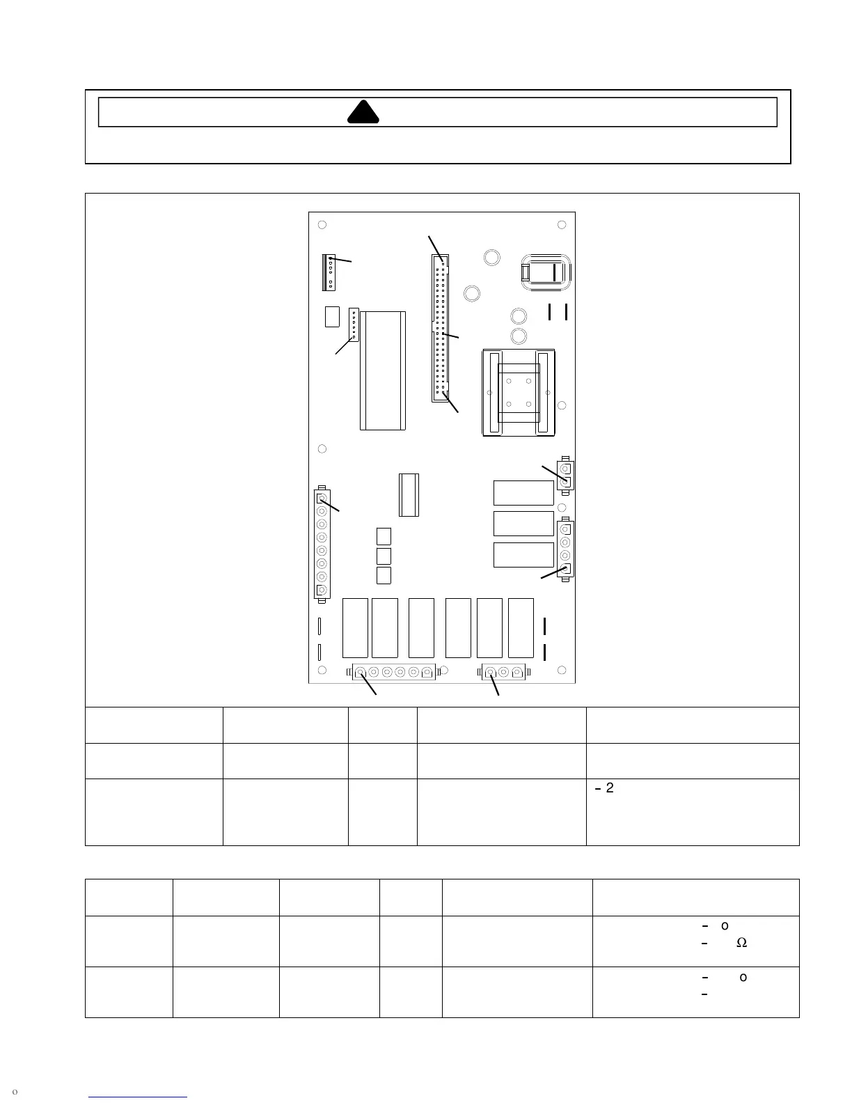
H.V. board
Pin 1
E1
E2E3
J5
J1
J2
E4
E5
J3
J4
E7
E6
J7
J6
J8
Pin 28
Pin 1
Pin 1
Pin 1
Pin 1Pin 1
Pin 1
Pin 1
Pin 50
Function Test Set-Up Meter
Setting
Probe Placement Results
Input to H.V. board At H.V. board Volts J1 pin 1 (Brown wire)
&J1pin2(Whitewire)
Line voltage
Output to display
board
Disconnect
J5 connector,
blower runs
continuously
Volts J5 pin 28 &
J5 pin 50
-
24 VDC
NOTE: For the following test, place oven in Service Test Mode (see page 21).
Relay Function Test Set-Up Meter
Setting
Probe Placement Results
K1 at
230 VAC
line voltage
Blower motor
Antenna motor
Cavity light
Disconnect
J2 connector
Ohms J1 pin 1 (Brown wire)
&J2pin4
Testmode5off
-
no continuity
Testmode5on
-
<1Ω
K2 at
208 VAC
line voltage
Blower motor
Antenna motor
Cavity light
Disconnect
J2 connector
Ohms J1 pin 1 (Brown wire)
&J2pin3
Testmode5off
-
no continuity
Testmode5on
-
<1Ω
 Loading...