Component Testing Procedures
!
WARNING
To avoid risk of electrical shock, personal injury or death; disconnect power to oven and discharge capacitor
before servicing, unless testing requires power.
RS2240003 Rev. 0 16
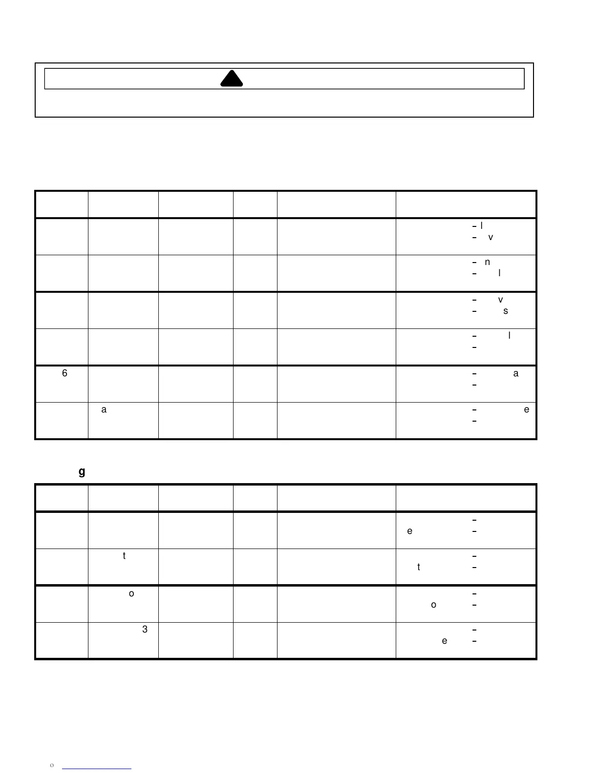
H.V. Board − Relay Test
Three Magnetron Models
Relay Function Test Set-Up Meter
Setting
Probe Placement Results
K8
Magnetron 1
(Top rear) at
230 VAC
All wires
connected to
H.V. board
VAC E2 (Black wire)
&J4pin2(Redwire)
Testmode1off
-
line voltage
Testmode1on
-
0volts
K9 Magnetron 1
(Top rear) at
208 VAC
All wires
connected to
H.V. board
VAC E2 (Black wire)
&J4pin1(Whitewire)
Testmode1off
-
line voltage
Testmode1on
-
0volts
K4
Magnetron 2
(Top front) at
230 VAC
All wires
connected to
H.V. board
VAC E5 (Red wire)
&J3pin1(Graywire)
Testmode2off
-
line voltage
Testmode2on
-
0volts
K5 Magnetron 2
(Top front) at
208 VAC
All wires
connected to
H.V. board
VAC E5 (Red wire)
& J3 pin 3 (Orange wire)
Testmode2off
-
line voltage
Testmode2on
-
0volts
K6
Magnetron 3
(Bottom) at
230 VAC
All wires
connected to
H.V. board
VAC J4 pin 4 (Black wire)
&J4pin6(Blackwire)
Testmode3off
-
line voltage
Testmode3on
-
0volts
K7 Magnetron 3
(Bottom) at
208 VAC
All wires
connected to
H.V. board
VAC J4 pin 4 (Black wire)
&J4pin5(Brownwire)
Testmode3off
-
line voltage
Testmode3on
-
0volts
Two Magnetron Models
Relay Function Test Set-Up Meter
Setting
Probe Placement Results
K8
Magnetron 1
(Top rear) at
230 VAC
All wires
connected to
H.V. board
VAC E5 (Red wire)
&J4pin2(Redwire)
Testmode1off
-
line voltage
Testmode1on
-
0volts
K9 Magnetron 1
(Top rear) at
208 VAC
All wires
connected to
H.V. board
VAC E5 (Red wire)
&J4pin1(Whitewire)
Testmode1off
-
line voltage
Testmode1on
-
0volts
K6
Magnetron 3
(Bottom) at
230 VAC
All wires
connected to
H.V. board
VAC J4 pin 4 (Black wire)
&J4pin6(Blackwire)
Testmode3off
-
line voltage
Testmode3on
-
0volts
K7 Magnetron 3
(Bottom) at
208 VAC
All wires
connected to
H.V. board
VAC J4 pin 4 (Black wire)
&J4pin5(Brownwire)
Testmode3off
-
line voltage
Testmode3on
-
0volts
 Loading...