28
Component Testing Procedures
!
WARNI NG
To avoid risk of electrical shock, personal injury or death, disconnect power to oven and discharge capacitor
before servicing, unless testing requires power.
Illustration Component Test Results
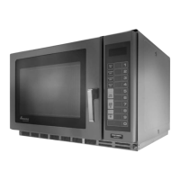
208
COM
230
120
Auto Transformer
230
208
120
0
Discharge Capacitors
Remove all wires from terminals.
Measure resistance from:
230 to 0...........................................................
208 to 0...........................................................
120 to 0...........................................................
42.4 .
38.6 .
21.5 .
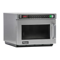
1
2
3
4
7
6
5
8
Terminal 1
230 V
Terminal 2
Common
Terminal 3
208 V
Transformer
# 4
1
3
2
# 5
# 6
7
8
1.0 F
-300 MA
-300 MA
1.0 F
Discharge Capacitors
Remove all wires from terminals.
Measure resistance from:
Terminal 1 to 2................................................
Terminal 1 to 3................................................
Terminal 5 to 6................................................
Terminal 7 to 8................................................
Terminal 4 to Ground screw on transformer...
Terminal 4 to any other terminal.....................
Gray
Violet
Red
12
3
1.0 .
Less than 1 .
Less than 1 .
Less than 1 .
30 .
Infinite resistance. If not, replace
transformer.
Primary /
Logic
Secondary
Mo nitor
Interlock switch
assembly
Disconnect wires to switch.
With door open measure resistance from:
Terminal C to NC Monitor..........................
Terminal C to NO Primary / Logic..............
Terminal C to NO Secondary ....................
With door closed measure resistance from:
Terminal C to NC Monitor..........................
Terminal C to NO Primary / Logic..............
Terminal C to NO Secondary ....................
Door Closed
Primary / Logic
C
NC
NO
C
C
NO
Secondary
Monitor
Continuity.
Infinite.
Infinite.
Infinite.
Continuity.
Continuity.
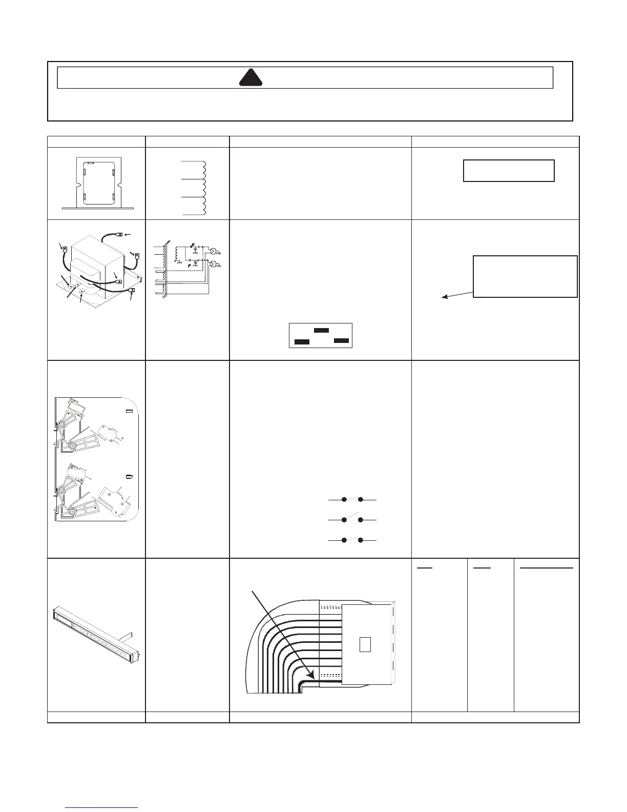
Touch Panel
Assembly
Continuity is indicated as 100 and below.
Pin 1: Ground.
Pad
1
2
3
4
5
6
7
8
9
0
Start
Stop/Reset
Power Level
X 2
Time Entry
Pins
8 & 10
7 & 10
6 & 10
5 & 10
4 & 10
3 & 10
8 & 9
7 & 9
6 & 9
5 & 9
4 & 9
4 & 8
5 & 8
6 & 8
7 & 8
Measurement
Continuity
Continuity
Continuity
Continuity
Continuity
Continuity
Continuity
Continuity
Continuity
Continuity
Continuity
Continuity
Continuity
Continuity
Continuity
Wire Harness Test continuity of wires ................................... Continuity.
Some models
Sample - Refer to Product
Tech Sheet for proper Ohm
resistance value.
 Loading...