29
Component Testing Procedures
!
WARNING
To avoid risk of electrical shock, personal injury or death, disconnect power to oven and discharge capacitor
before servicing, unless testing requires power.
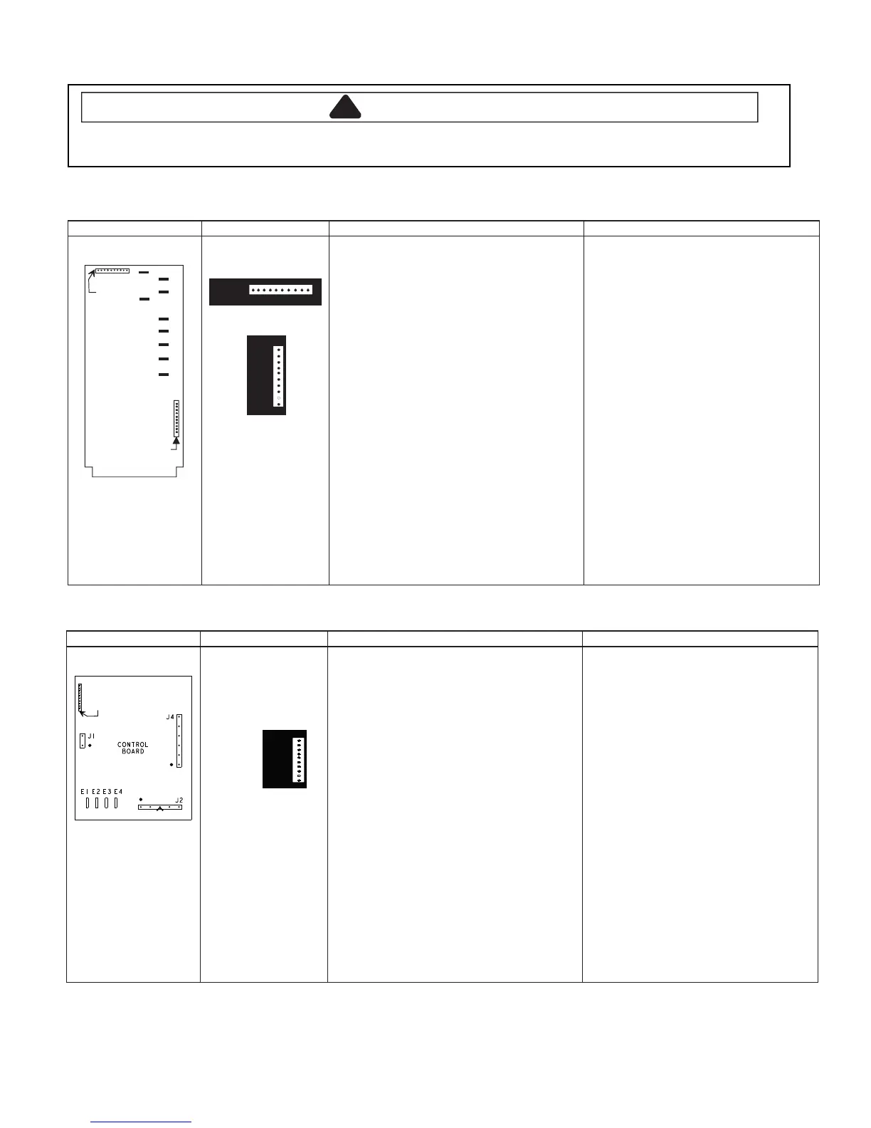
Illustration Component Test Results
Pin #1
Pin #1
P1
P2
A
B
C
D
E
F
G
L
H
Control board
P2
1
10
P1
1
10
P1 connector used
for touch panel
ribbon
All Models
Line voltage to control board
P2 connector
Pin 1—Pin 3 ..............................................
Output drive voltage to triac
Triac terminals.............................................
Gate—T1...................................................
208 VAC line voltage
Fan relay (controls blower motor, antenna
motor(s), and oven light)
Control board...............................................
Terminals C—D.........................................
Line voltage sensing relay (automatically
switches for 208 or 230 VAC operation)
Control board...............................................
Terminals F—G .........................................
230 VAC line voltage
Fan relay (controls blower motor, antenna
motor(s), and oven light)
Control board...............................................
Terminals C—E .........................................
Line voltage sensing relay (automatically
switches for 208 or 230 VAC operation)
Control board...............................................
Terminals F—H .........................................
Line voltage (All Conditions)
0 VAC (Idle and Standby)
0.9 VAC (Cook)
Line voltage (Idle)
0 VAC (Standby and Cook)
Line voltage (Idle)
0 volts (Standby and Cook)
Line voltage (Idle)
0 VAC (Standby and Cook)
Line voltage (Idle)
0 volts (Standby and Cook)
Illustration Component Test Results
CONTROL
BOARD
J2
J1
J4
E1 E2 E3 E4
Pin #1
P1
Control board
P1
1
10
P1 connector used
for touch panel
ribbon
All Models
Line voltage to control board
E1 (RD) —T1 (BK) triac ............................
Output drive voltage to triac
Triac terminals.............................................
Gate (BR) —T1 (BK) .................................
208 VAC line voltage
Fan relay (controls blower motor, antenna
motor(s), and oven light)
Control board...............................................
Terminals T1 (BK) —J2-3 (RD).................
Line voltage sensing relay (automatically
switches for 208 or 230 VAC operation)
Control board...............................................
Terminals E1 (RD)—E2 (VT) ....................
230 VAC line voltage
Fan relay (controls blower motor, antenna
motor(s), and oven light)
Control board...............................................
Terminals T1 (BK) —J2-3 (RD).................
Line voltage sensing relay (automatically
switches for 208 or 230 VAC operation)
Control board...............................................
Terminals E1 (RD) —E4 (PK) ...................
Line voltage (All Conditions)
0 VAC (Idle and Standby)
0.9 VAC (Cook)
Line voltage (Idle)
0 VAC (Standby and Cook)
Line voltage (Idle)
0 volts (Standby and Cook)
Line voltage (Idle)
0 VAC (Standby and Cook)
Line voltage (Idle)
0 volts (Standby and Cook)
Invensy Control Board
CPI Control Board
 Loading...