Component Testing Procedures
WARNING
To avoid risk of electrical shock, personal injury, or death, disconnect power to oven and discharge capacitor
before servicing, unless testing requires it.
RS2240002 Rev. 1 19
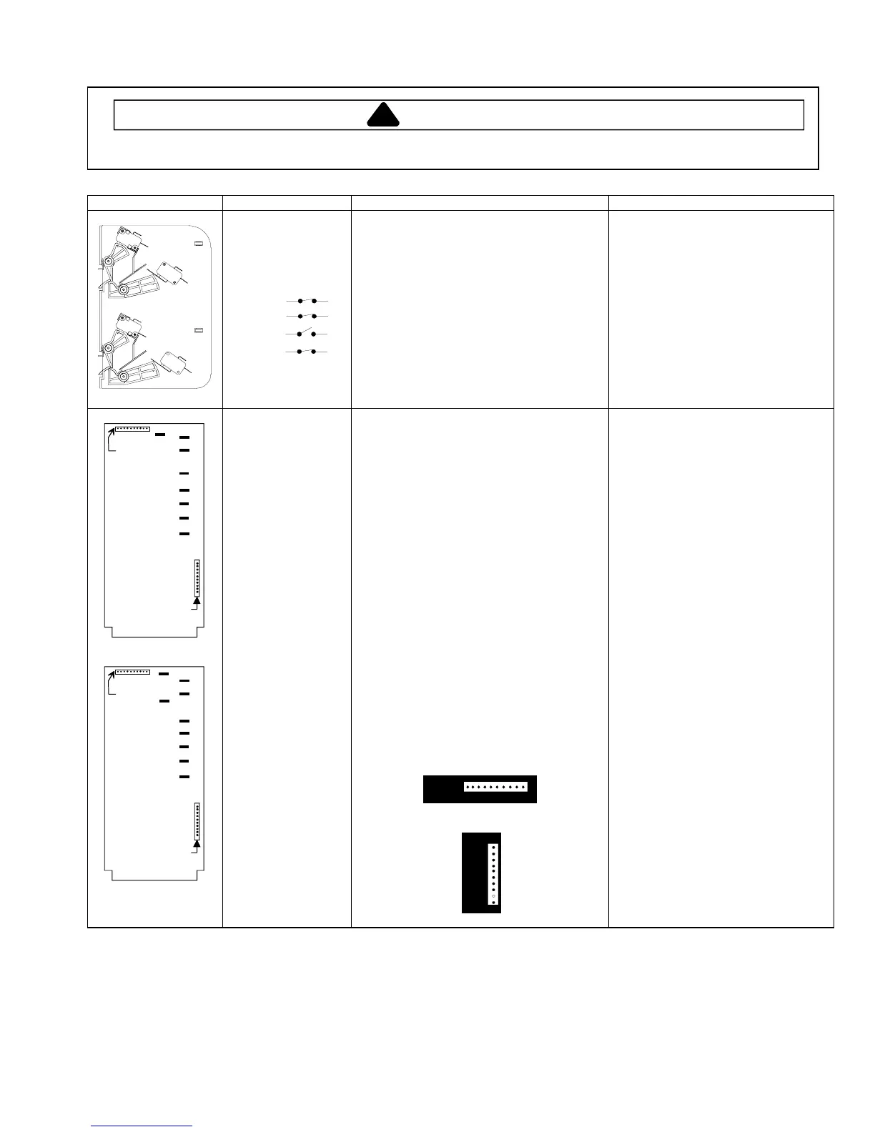
Illustration Component Testing Results
R0000277
Primary
Logic
Secondary
Monitor
COM
N.O.
COM
COM
COM
N.O.
N.O.
N.C.
Interlock switch
assembly
Door Closed
Logic
C
NC
NO
C
C
NO
Secondary
Monitor
Primary
C
NO
Disconnect wires to switch.
With door open measure resistance from:
Terminal C to NO Primary
Terminal C to NO Logic
Terminal C to NC Monitor
Terminal C to NO Secondary
With door closed measure resistance from:
Terminal C to NO Primary
Terminal C to NO Logic
Terminal C to NC Monitor
Terminal C to NO Secondary
Infinite
Infinite
Indicates continuity
Infinite
Indicates continuity
Indicates continuity
Infinite
Indicates continuity
Type 1
Pin #1
Pin #1
P1
P2
A B C D E F G
H
Type 2
Pin #1
Pin #1
P1
P2
A B C D E F G
L
H
Controller board
Type 1
CRC18T2OG
P1323006M
CRC21T2RL
P1323007M
HDC18
P1323003M
HDC18SD
P1323004M
HDC21
P1323005M
Type 2
CRC18T2OG
P1323015M
CRC21T2RL
P1323017M
HDC18
P1323013M
HDC18SD
P1323014M
HDC21
P1323016M
All Models
Line voltage to control board
P2 connector
Pin 1 — Pin 3 .......................................
Output drive voltage to triac
Triac terminals
Gate — T1............................................
208 VAC line voltage
Fan relay (controls blower motor, antenna
motor(s), and oven light)
Control board..........................................
Terminals C — D..................................
Line voltage sensing relay (automatically
switches for 208 or 230 VAC operation)
Control board..........................................
Terminals F — G..................................
230 VAC line voltage
Fan relay (controls blower motor, antenna
motor(s), and oven light)
Control board..........................................
Terminals C — E..................................
Line voltage sensing relay (automatically
switches for 208 or 230 VAC operation)
Control board..........................................
Terminals F — H ..................................
P2
1
10
P1
1
10
Line voltage (All Condition)
0 VAC (Idle and Standby)
0.9 VAC (Cook)
Line voltage (Idle)
0 VAC (Standby and Cook)
Line voltage (Idle)
0 volts (Standby and Cook)
Line voltage (Idle)
0 VAC (Standby and Cook)
Line voltage (Idle)
0 volts (Standby and Cook)
P1 connector used for touch panel
ribbon
 Loading...