Need help?
Do you have a question about the Amana GSXH5 Series and is the answer not in the manual?
Key safety warnings including high voltage, qualified personnel, and bypassing devices.
Verify unit specifications, model, and accessories upon delivery.
Ensure installation complies with all applicable national and local codes.
Specifies minimum clearances around the unit for proper airflow.
Addresses structural support, weather-tightness, and vibration reduction.
Details safe practices for handling refrigerants to prevent injury and death.
Guidelines for installing and insulating refrigerant lines to prevent damage.
Procedures for handling existing refrigerant lines when replacing components.
Checklist for safely burying refrigerant lines underground.
Proper techniques for brazing refrigerant lines, including preparation and safety.
Methods for performing pressure tests to detect refrigerant leaks.
Steps for conducting a standing pressure test to verify system integrity.
Warnings regarding refrigerant pressure and compressor operation during evacuation.
Recommended procedure for achieving a deep vacuum in the system.
High voltage warnings and guidelines for proper electrical wiring.
Diagram for connecting a two-stage thermostat with three low voltage wires.
Diagram for connecting a single-stage thermostat with two low voltage wires.
Approved overcurrent protection devices for the system.
Procedure for verifying three-phase compressor rotation.
Routing and termination of high voltage power supply wires.
Routing and termination of low voltage control wires.
Cautionary note on opening service valves to avoid refrigerant leaks.
Correct power sequence for outdoor units with ECM motors.
Guidelines for adding refrigerant based on line set length.
Warnings regarding overcharging, vacuum operation, and potential damage.
Methods and targets for verifying system charge using superheat and subcooling.
Precautions and procedures for charging fixed orifice systems.
Table of target superheat values for piston match-up systems.
Chart relating suction pressure to saturated suction temperature for R-410A.
Chart relating liquid pressure to saturated liquid temperature for R-410A.
Formula for calculating subcooling and procedure for TXV systems.
Formula for calculating superheat and procedure for TXV systems.
Tables of target superheat settings for various TXV systems.
Guide to diagnose and remedy common system complaints.
Importance and procedure for maintaining the air filter.
Guidelines for cleaning the outdoor coil by a qualified servicer.
Checks to perform before contacting a service technician.
Required electrical measurements for system start-up.
Required temperature measurements for system start-up.
Required pressure measurements for system start-up.
Check for superheat and subcooling values.
Other checks to perform during start-up.
Information on providing feedback for Goodman and Amana products.
Instructions and benefits of registering your product.
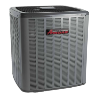
This manual describes a condensing unit for air conditioning systems, providing comprehensive instructions for its installation, operation, and maintenance. The unit is designed to work in conjunction with an indoor evaporator coil to provide cooling for residential and light commercial applications.
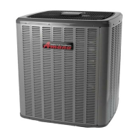
The condensing unit is a critical component of a split air conditioning system. Its primary function is to reject heat from the refrigerant to the outdoor air, thereby cooling the indoor space. The unit contains a compressor, condenser coil, and an outdoor fan. The compressor circulates refrigerant through the system, increasing its pressure and temperature. The hot, high-pressure refrigerant then flows through the condenser coil, where the outdoor fan draws air across the coil, facilitating heat transfer from the refrigerant to the ambient air. As the refrigerant cools, it condenses into a liquid and then flows to the indoor evaporator coil to absorb heat from the indoor air, completing the refrigeration cycle.
The unit is approved for operation in cooling mode at outdoor temperatures above 55°F. For operation below 55°F, an approved low ambient kit is required, though it cannot be used with outdoor units containing ECM motors. The system is designed to achieve rated performance after 20 hours of operation and at the specified airflow.
The condensing unit is designed for both ground-level and rooftop installations. For ground-level installations, it requires a solid, level foundation that will not shift or settle, preferably a concrete slab raised above ground level to minimize sound transmission. For rooftop installations, the roof structure must be capable of supporting the unit's weight, and proper consideration must be given to weather-tight integrity. Vibration absorbing pads or springs can be installed to reduce noise transmission.
Proper installation clearances are crucial for optimal air circulation and performance. The top of the unit should ideally be unobstructed. If vertical obstructions are present, a minimum of 60 inches of clearance between the top of the unit and the obstruction is required. Corner installations are strongly discouraged to ensure adequate service clearance and airflow.
The unit utilizes refrigerant-grade (dehydrated and sealed) copper tubing for connecting to the indoor evaporator. It is essential to keep the tubing clean and dry during installation to prevent contamination. Refrigerant lines should not come into direct contact with plumbing, ductwork, floor joists, wall studs, floors, or walls to avoid sound and vibration transmission. Openings through foundations or walls for refrigerant lines should be filled with pliable silicon-based caulk, RTV, or vibration damping material. The suction line must always be insulated to prevent condensation.
The manual provides recommended interconnecting tubing sizes based on tonnage and line length. For longer line lengths or significant vertical elevation changes, specific application guidelines (TP-107 R-410A Long Line Set Application Guidelines) should be consulted.
For existing line sets, it is recommended to drain as much residual compressor oil as possible and use an approved flushing agent followed by a nitrogen purge to remove any remaining agent or contaminants. Replacement of the indoor coil is also recommended in such cases.
Burying refrigerant lines should be avoided if possible. If necessary, both liquid and suction lines must be insulated separately and enclosed in waterproof material (conduit or pipe), with ends sealed where tubing enters/exits the enclosure. Lines passing under or through a concrete slab require adequate protection and sealing.
Refrigerant line connections involve brazing, and it is crucial to protect sensitive components like service valves, TXV valves, or filter driers from overheating by wrapping them with a wet rag or using a thermal heat trap compound. Schrader valves must be removed from service valves before brazing. A brazing alloy with a minimum of 2% silver content should be used, and flux must be avoided. Nitrogen or inert gas should be swept through the refrigerant lines during brazing to prevent copper-oxide formation, which can lead to blockages or metering device failure. After brazing, joints should be quenched with water or a wet cloth. The filter drier paint finish should be inspected and repainted if burned or chipped to prevent rust.
A standing pressure test with dry nitrogen (up to 450 PSIG) is recommended before system evacuation to check for leaks. If a leak is detected, the procedure for leak testing (nitrogen or nitrogen-traced) should be followed.
Electrical connections must comply with national and local codes. High voltage power supply and ground wires should be routed through the high voltage port, and low voltage control wiring (24 Volt minimum, 25VA) through the low voltage port. For three-phase compressors, proper rotation must be verified by observing suction and discharge pressures. If rotation is reversed, two leads at the unit contactor should be switched.
System startup involves opening service valves until the stem is 1/8" from the retainer to avoid refrigerant loss. The service valve caps are secondary seals and must be properly tightened. Power must be supplied to outdoor units with ECM motors before applying power to the indoor unit to prevent control module malfunction.
The unit is pre-charged with adequate refrigerant for the matching HSVTC evaporator coil and 15 feet of line set. For other evaporator coils or longer line sets, refrigerant may need to be added or removed to achieve proper charge. Charge should always be checked using superheat for piston-equipped indoor coils and subcooling for TXV-equipped indoor coils.
The manual emphasizes the importance of regular maintenance for split air conditioning and heat pump systems, recommending a bi-annual checkup by a qualified servicer before the heating and cooling seasons.
Filter replacement or cleaning is a key maintenance task. The indoor air filter must always be installed, as operating the unit without a filter can lead to dust and lint buildup, reduced efficiency, equipment damage, and fire hazards. Filters should be checked at least once a month and replaced or cleaned as needed. High-efficiency electronic or non-electronic filters can be used to capture smaller airborne particles.
The compressor motor is hermetically sealed and does not require additional oiling. Similarly, outdoor and indoor fan motors are permanently lubricated and do not require additional oiling.
Cleaning the outdoor coil is essential for maintaining proper airflow and efficiency. This task should be performed by a qualified servicer, as inexperienced individuals could easily damage the tubing. Dirt, leaves, or debris can restrict airflow. Constructing fences, decks, or patios near the unit should be discussed with a dealer or qualified servicer to avoid restricting airflow. Using a condensing unit cover during winter is generally not recommended unless it is a "breathable" fabric to prevent moisture buildup.
Before calling a servicer for troubleshooting, users should check the thermostat settings, wait 15 minutes for the system to reset, check for tripped circuit breakers or failed fuses, ensure the disconnect switch near the indoor furnace or blower is closed, check for obstructions on the outdoor unit, confirm indoor air inlets and outlets are clear, check and clean/replace the filter, and listen for any unusual noises. If a circuit breaker or fuse repeatedly opens, a qualified servicer should be contacted to correct the underlying problem to prevent severe equipment damage.
 General
| Refrigerant | R-410A |
|---|---|
| Noise Level | As low as 72 dB |
| Cooling Stages | Single Stage |
| Sound Level | As low as 72 dB |
| Warranty | 10-Year Parts Limited Warranty |

 To Next Page