EasyManua.ls Logo

Amana SZC 160241 - User Manual

Amana SZC 160241
24 pages
Print Icon
To Next Page IconTo Next Page
Loading...
IMPORTANT SAFETY INSTRUCTIONS
The following symbols and labels are used throughout this
manual to indicate immediate or potential safety hazards.
It is the owner’s and installer’s responsibility to read
and comply with all safety information and instructions
accompanying these symbols. Failure to heed safety
information increases the risk of personal injury, property
damage, and/or product damage.
WARNING

-
-




-

-
-















-


WARNING
WARNING

CONDENSING UNIT
HEAT PUMP

© 2020-2023



 
CAUTION




SHIPPING INSPECTION
Always keep the unit upright; laying the unit on its side
or top may cause equipment damage. Shipping damage,
and subsequent investigation is the responsibility of

electrical characteristics, and accessories are correct
prior to installation. The distributor or manufacturer will not
accept claims from dealers for transportation damage or
installation of incorrectly shipped units.
CODES & REGULATIONS
This product is designed and manufactured to comply
with national codes. Installation in accordance with such
codes and/or prevailing local codes/regulations is the
responsibility of the installer. The manufacturer assumes
no responsibility for equipment installed in violation of any
codes or regulations. Rated performance is achieved after
20 hours of operation. Rated performance is delivered at



sheets can be found at www.goodmanmfg.com for
Goodman® brand products or www.amana-hac.com for
Amana
®
brand products. Within either website, please
select the residential or commercial products menu and
then select the submenu for the type of product to be
installed, such as air conditioners or heat pumps, to access
a list of product pages that each contain links to that

The United States Environmental Protection Agency


follow these regulations may harm the environment

19001 Kermier Rd., Waller, TX 77484
www.goodmanmfg.com • www.amana-hac.com
© 2021-2023 Daikin Comfort Technologies Manufacturing, L.P.
is a registered trademark of Maytag Corporation or its related companies
and is used under license. All rights reserved.
Question and Answer IconNeed help?

Do you have a question about the Amana SZC 160241 and is the answer not in the manual?

Summary

Safety Instructions

General Safety Precautions

Covers critical warnings for high voltage, qualified personnel, and safety device integrity.

Shipping and Regulatory Compliance

Details shipping inspection procedures and adherence to codes and regulations.

System Features

ComfortBridge Technology

Explains the ComfortBridge system for enhanced control and diagnostics.

Installation Guidelines

Site Selection and Clearances

Specifies required clearances and placement considerations for optimal airflow.

Foundation and Rooftop Mounting

Covers requirements for ground-level foundations and rooftop installation stability.

Refrigerant Lines

Tubing Specifications and Installation

Guidelines for selecting and installing refrigerant tubing, including insulation and routing.

Refrigerant Line Clearances

Details required clearances for refrigerant lines to prevent contact and vibration.

Safe Refrigerant Handling

General Handling Precautions

Provides essential safety warnings for handling refrigerants to avoid injury or death.

Explosion Prevention Measures

Outlines critical safety measures to prevent explosions when handling refrigerant cylinders.

Existing Line Sets

Compatibility and Cleaning Procedures

Ensures compatibility with new refrigerants and outlines system cleaning steps.

Refrigerant Line Installation

Line Connections and Brazing

Covers safe brazing techniques and proper line connections for refrigerant integrity.

Underground and Leak Testing

Details burying lines and performing nitrogen leak tests for system integrity.

System Evacuation

Evacuation Procedures and Pressure Tests

Describes pressure testing and system evacuation to remove air and moisture.

Deep Vacuum Method

Explains the recommended Deep Vacuum Method for efficient system evacuation.

Electrical System Setup

High Voltage and Wire Sizing

Covers high voltage connections, wire sizing, and overcurrent protection requirements.

Electrical System Wiring

High Voltage Wiring

Details routing power supply and ground wires through the high voltage port.

Low Voltage Wiring

Explains low voltage connections for both communicating and legacy systems.

System Start Up

Pre-Start Checks and Cautions

Important cautions before starting the system, including refrigerant leak warnings.

Final Charge Adjustment

Pre-Charge Verification Steps

Outlines checks for airflow and static pressure before adjusting refrigerant charge.

Superheat and Subcooling Adjustments

Provides guidelines for superheat adjustments in cooling and heating cycles.

Charge Verification

Refrigerant Handling Safety

Reinforces safety warnings regarding refrigerant pressure and handling during charging.

Expansion Valve System

Suction Pressure and Temperature Chart

Provides data correlating suction pressure with saturated suction temperature.

Liquid Pressure and Temperature Chart

Offers data relating liquid pressure to saturated liquid temperature.

Charge Verification Method

Details the process of measuring subcooling for system charge verification.

Heat Pump Heating Cycle

Heating Mode Charging and Lock-out

Explains charging in heat mode and the low speed lock-out feature.

Advanced Adjustment Recommendations

Superheat and Subcooling Adjustments

Provides detailed guidance for adjusting superheat and subcooling for TXV systems.

ComfortBridge System

System Overview and Features

Describes the ComfortBridge system's digital communication and advanced features.

Airflow Considerations

Airflow Management in Communicating Systems

Explains how airflow is managed in communicating vs. legacy systems.

Airflow Tables for Heat Pumps

Lists nominal airflow rates for ComfortBridge heat pumps in cooling and heating.

Control Wiring

Thermostat Wiring and Communication

Details thermostat signal types and communication wiring for system setup.

Two-Wire Outdoor Connections

Explains the two-wire wiring scheme for communicating systems between units.

Legacy Controls Wiring

System Wiring Configuration

Details wiring for legacy systems, including connector changes and transformer disconnection.

ComfortBridge System Features

Advanced Features and Fault History

Covers access to system info, advanced setup, and fault code history retrieval.

Device Settings and Airflow Profiles

Explains how to adjust cooling performance variables and airflow profiles.

Heat Set-Up

Heating Performance Adjustments

Allows adjustment of heating trim, delays, defrost interval, and compressor delay.

System Configuration

Device Status Monitoring

Displays current system operational mode and requested indoor CFM for troubleshooting.

Thermostat Integration

Describes thermostat settings for dual-fuel systems and balance point configuration.

System Troubleshooting

Troubleshooting Guide Reference

Directs users to the troubleshooting chart for error codes and corrective actions.

Troubleshooting Information

Condensing Unit Common Issues

Lists common complaints, possible causes, and diagnostic test methods for the condensing unit.

Unitary Diagnostic Codes: Overview

System Fault Code Descriptions

Details specific diagnostic codes for system faults, possible causes, and corrective actions.

Unitary Diagnostic Codes: Communication Faults

Communication and System Mismatch Faults

Covers faults related to network data, communication, and system mismatches.

Unitary Diagnostic Codes: Compressor Operation Faults

Short Cycling and Locked Rotor Faults

Addresses issues like short cycling, locked rotor, and open circuits in compressor operation.

Unitary Diagnostic Codes: Pressure Switch Faults

High Pressure and Low Pressure Lockouts

Details faults related to high and low pressure cut-outs and lockouts.

Unitary Diagnostic Codes: Circuit Faults

Compressor Protection and Circuit Faults

Covers faults like short cycling, locked rotor, and open circuits affecting compressor operation.

Unitary Diagnostic Codes: Voltage Faults

Voltage and Pilot Voltage Faults

Explains faults related to high/low line voltage, low pilot voltage, and open circuits.

Unitary Diagnostic Codes: Voltage and Compressor Faults

Voltage and Compressor Circuit Issues

Details faults for high/low line voltage, low pilot voltage, and compressor circuit problems.

Routine Maintenance Recommendations

Filter Replacement and Cleaning

Importance of using and maintaining indoor air filters for system efficiency and longevity.

Component Lubrication

Notes that compressor and fan motors are permanently lubricated and require no additional oiling.

Outdoor Coil Cleaning

Advises on the necessity of keeping the outdoor coil clean and hiring a servicer for cleaning.

Pre-Servicer Checks

Lists checks to perform before calling a servicer, such as thermostat settings and circuit breakers.

Start-Up Checklist

Electrical and Voltage Measurements

Details electrical checks including line voltage, secondary voltage, and component amperage.

Temperature and Pressure Readings

Lists required indoor/outdoor temperature and pressure readings for system verification.

Superheat, Subcooling, and Line Set

Specifies measurements for superheat, subcooling, and line set length for proper charge.

Customer Feedback

Providing Product Comments

Encourages users to provide feedback via online forms or QR codes.

Product Registration

Warranty Registration Process

Guides users on how to register their product for enhanced warranty protection.

Overview

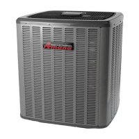
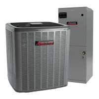
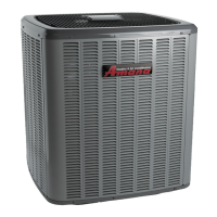
This document is an installation and service reference manual for a Condensing Unit Heat Pump, covering models from 2020-2023 manufactured by Daikin Comfort Technologies Manufacturing, L.P. It provides essential information for qualified personnel regarding the safe and proper installation, operation, and maintenance of the equipment.

Function Description

The condensing unit heat pump is designed for residential and light commercial applications, providing both heating and cooling. It can operate as part of a fully communicating HVAC system utilizing ComfortBridge™ compatible indoor units, or as a non-communicating (legacy) system with 24 VAC inputs and outputs. The system manages airflow demands based on the operating mode, with either the indoor unit, outdoor unit, or thermostat determining the airflow demand for the ECM motor.

Important Technical Specifications

  • Refrigerant: The units are designed for R-410A refrigerant.
  • Electrical: The unit's rating plate lists pertinent electrical data for proper service and overcurrent protection. Wires should be sized to limit voltage drop to 2% (max.) from the main breaker or fuse panel.
  • Overcurrent Protection: Approved devices include time delay fuses and HACR type circuit breakers.
  • Low Voltage Control: For communicating systems, only two low voltage control wires are required between the outdoor and indoor units. For non-communicating systems, the outdoor unit transformer must be disconnected from low and line voltage connections.
  • Defrost Time Interval: For non-communicating systems, defrost time intervals can be selected via dipswitch settings (30, 60, 90, 120 minutes). The factory default is 30 minutes, with a maximum defrost cycle time of 10 minutes.
  • Refrigerant Charge: Adequate refrigerant charge for the matching evaporator coil or air handler and 15 feet of lineset is supplied with the condensing unit. For linesets exceeding 15 feet, refrigerant should be added at 0.6 ounces per foot of liquid line.
  • Subcooling: TXV-based systems should have a Subcooling value of 6°F +/- 1°F.
  • Superheat: TXV-based systems should have a Superheat value of 8°F +/- 1°F.
  • Low Speed Lock-Out: The outdoor system has a low speed lock-out feature. In communicating mode, below 37°F outdoor ambient, the system locks out low stage and operates only in high stage to provide maximum heating capacity.
  • Airflow Profiles: The system offers four cooling airflow profiles (A, B, C, D) with varying ramp-up and OFF delay characteristics to optimize cooling demand airflow.
  • Line Set Length: Recommended interconnecting tubing sizes are provided for line lengths of 0-24 ft, 25-49 ft, and 50-79 ft. For runs exceeding 79 feet or with vertical elevation changes over 50 feet, refer to TP-107 Long Line Set Application R-410A guidelines.

Usage Features

  • Safety: The manual emphasizes critical safety instructions, including warnings about high voltage, proper refrigerant handling, and the need for trained personnel for installation and servicing. It also warns against using scroll compressors to evacuate the AC system due to potential damage.
  • Shipping Inspection: Users are instructed to keep the unit upright during shipping, verify model numbers and specifications, and report any shipping damage to the carrier.
  • Codes & Regulations: The product complies with national codes, and installers are responsible for adhering to local codes and EPA regulations regarding refrigerants.
  • Installation: Detailed instructions are provided for site selection, including minimum elevation recommendations for severe weather, and considerations for rooftop installations to minimize vibration and noise.
  • Refrigerant Line Handling: Guidelines include using only refrigerant-grade copper tubing, keeping tubing clean and dry, cutting ends square, and preventing direct contact with building structures. Insulation of the suction line is required to prevent condensation.
  • Brazing: Instructions for brazing include using a wet rag or thermal heat trap compound to protect components, using a 2% minimum silver content brazing alloy, and sweeping lines with nitrogen to prevent copper-oxide formation.
  • Leak Testing: The system should be pressurized with dry nitrogen to 450 PSIG and checked for leaks using soapy water or an electronic leak detector.
  • System Evacuation: The Deep Vacuum Method is recommended, requiring a vacuum pump rated for 500 microns or less. The system should be evacuated to less than 500 microns and hold vacuum for 10 minutes.
  • Electrical Connections: Wiring must conform to NEC or CEC and local codes. The manual specifies routing power and ground wires through the high voltage port and control wires through the low voltage port.
  • System Start-Up: Service valves should be opened until the top of the stem is 1/8" from the retainer to avoid refrigerant loss.
  • Charge Verification and Adjustment: The manual outlines procedures for checking airflow and total static pressure, and for adjusting refrigerant charge using subcooling for TXV-equipped coils or superheat for adjustable TXVs.
  • Heat Pump - Heating Cycle: Charging in heat mode is done by weight, with adjustments for line size and length. Final charge adjustments are made in the cooling cycle.
  • ComfortBridge™ System: This advanced feature enables digital communication between indoor and outdoor units, allowing access to additional system information, advanced setup, and diagnostic/troubleshooting features via push buttons or the CoolCloud mobile app.
  • Fault Code History: The system stores the last six faults detected, providing diagnostic information for troubleshooting.

Maintenance Features

  • Routine Maintenance: Bi-annual maintenance checkups by a qualified servicer are strongly recommended before heating and cooling seasons.
  • Filter Replacement/Cleaning: Filters must be used and checked monthly. Dirty filters should be replaced or cleaned to prevent efficiency loss and equipment damage.
  • Compressor: The compressor motor is hermetically sealed and does not require additional oiling.
  • Motors: Indoor and outdoor fan motors are permanently lubricated and do not require additional oiling.
  • Outdoor Coil Cleaning: Qualified servicers should clean the outdoor coil to maintain airflow and prevent equipment damage. The manual advises against constructing fences or decks that restrict airflow.
  • Troubleshooting: The manual includes detailed troubleshooting charts for unitary diagnostic codes, listing symptoms, LED display codes, fault descriptions, possible causes, corrective actions, and notes/cautions.
  • Pre-Service Checks: Before calling a servicer, users are advised to check thermostat settings, wait 15 minutes for automatic resets, check electrical panels for tripped breakers or failed fuses, confirm disconnect switch closure, check for outdoor unit obstructions, and verify indoor air inlet/outlet blockage and filter cleanliness.

Amana SZC 160241 Specifications

General IconGeneral
BrandAmana
ModelSZC 160241
CategoryHeat Pump
LanguageEnglish

Related product manuals