I
MPORTANT
S
AFETY
I
NSTRUCTIONS
The following symbols and labels are used throughout this
manual to indicate immediate or potential safety hazards. It is
the owner’s and installer’s responsibility to read and comply with
all safety information and instructions accompanying these sym-
bols. Failure to heed safety information increases the risk of
personal injury, property damage, and/or product damage.
HIGH VOLTAGE !
D
ISCONNECT
ALL
POWER
BEFORE
SERVICING
.
M
ULTIPLE
POWER
SOURCES
MAY
BE
PRESENT
. F
AILURE
TO
DO
SO
MAY
CAUSE
PROPERTY
DAMAGE
,
PERSONAL
INJURY
OR
DEATH
.
WARNING
O
NLY
PERSONNEL
THAT
HAVE
BEEN
TRAINED
TO
INSTALL
,
ADJUST
,
SERVICE
OR
REPAIR
(
HEREINAFTER
, “
SERVICE
”)
THE
EQUIPMENT
SPECIFIED
IN
THIS
MANUAL
SHOULD
SERVICE
THE
EQUIPMENT
. T
HE
MANUFACTURER
WILL
NOT
BE
RESPONSIBLE
FOR
ANY
INJURY
OR
PROPERTY
DAMAGE
ARISING
FROM
IMPROPER
SERVICE
OR
SERVICE
PROCEDURES
. I
F
YOU
SERVICE
THIS
UNIT
,
YOU
ASSUME
RESPONSIBILITY
FOR
ANY
INJURY
OR
PROPERTY
DAMAGE
WHICH
MAY
RESULT
. I
N
ADDITION
,
IN
JURISDICTIONS
THAT
REQUIRE
ONE
OR
MORE
LICENSES
TO
SERVICE
THE
EQUIPMENT
SPECIFIED
IN
THIS
MANUAL
,
ONLY
LICENSED
PERSONNEL
SHOULD
SERVICE
THE
EQUIPMENT
. I
MPROPER
INSTALLATION
,
ADJUSTMENT
,
SERVICING
OR
REPAIR
OF
THE
EQUIPMENT
SPECIFIED
IN
THIS
MANUAL
,
OR
ATTEMPTING
TO
INSTALL
,
ADJUST
,
SERVICE
OR
REPAIR
THE
EQUIPMENT
SPECIFIED
IN
THIS
MANUAL
WITHOUT
PROPER
TRAINING
MAY
RESULT
IN
PRODUCT
DAMAGE
,
PROPERTY
DAMAGE
,
PERSONAL
INJURY
OR
DEATH
.
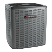
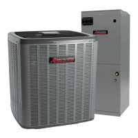
HEAT PUMP UNIT
AVZC20 HEAT PUMP
INSTALLATION & SERVICE REFERENCE
Index
All information contained herein is subject to change without notice.
© 2015 - 2016 Goodman Manufacturing Company, L.P.
5151 San Felipe St., Suite 500, Houston, TX 77056
www.amana-hac.com
is a registered trademark of Maytag Corporation or its related companies and is used under license. All rights reserved.
IOA-4013C
8/2016
IMPORTANT SAFETY INSTRUCTIONS .......................................... 1
SHIPPING INSPECTION ............................................................ 2
CODES & REGULATIONS ........................................................ 2
FEATURES ............................................................................ 2
INSTALLATION CLEARANCES .................................................... 2
ROOFTOP INSTALLATIONS ........................................................ 3
SAFE REFRIGERANT HANDLING ............................................... 3
REFRIGERANT LINES .............................................................. 3
REFRIGERANT LINE CONNECTIONS........................................... 5
LEAK TESTING (NITROGEN OR NITROGEN-TRACED) ................... 5
SYSTEM START-UP PROCEDURE.............................................. 5
ELECTRICAL CONNECTIONS .................................................... 6
HEAT PUMP ADVANCED FEATURE MENU ............................... 22
WIRING DIAGRAM ............................................................... 25
CAPACITOR ........................................................................ 28
TROUBLESHOOTING .............................................................. 33
S
ETTING THE MODE DISPLAY ............................................... 38
7-S
EGMENT DISPLAY ........................................................... 44
START-UP CHECKLIST .......................................................... 47
“IMPORTANT – THIS PRODUCT HAS BEEN DESIGNED AND MANUFACTURED TO MEET ENERGY STAR CRITERIA FOR
ENERGY EFFICIENCY WHEN MATCHED WITH APPROPRIATE COIL COMPONENTS. HOWEVER, PROPER REFRIGERANT CHARGE
AND PROPER AIR FLOW ARE CRITICAL TO ACHIEVE RATED CAPACITY AND EFFICIENCY. INSTALLATION OF THIS PRODUCT SHOULD
FOLLOW THE MANUFACTURER’S REFRIGERANT CHARGING AND AIR FLOW INSTRUCTIONS. FAILURE TO CONFIRM PROPER
CHARGE AND AIRFLOW MAY REDUCE ENERGY EFFICIENCY AND SHORTEN EQUIPMENT LIFE.”