16
Backup heat lockout temperature will enable auxiliary/sec-
ondary heating to be turned on when outdoor temperature is
much higher than indoor temperature, compressor might stop
operating under this circumstance.
Line Set Length Range
(feet)
Compressor Lockout Temperature
(°F)
0 to 100 15
100 to 200 20
In order to access temperature, the compressor lockout and
the backup heat lockout, press MENU and scroll down to
press INSTALLER OPTIONS. Enter the date code (password)
when prompted. Choose VIEW / EDIT CURRENT SETUP and
COMPRESSOR LOCKOUT / BALANCE POINT will be under
HEAT / COOL CONTROL OPTIONS. For more information
please refer to COMFORTNET™ CTK04 Communicating Ther-
mostat SYSTEM INSTALLATION GUIDE.
BOOST MODE
BOOST MODE enables the system to operate at a higher com-
pressor speed than rated maximum compressor speed and
satisfy the structural load more effectively during higher
ambient outdoor conditions. BOOST MODE is initiated by
an outdoor temperature sensor located in the outdoor unit.
Please note that outdoor equipment operational sound lev-
els may increase while the equipment is running in BOOST
MODE. Disabling BOOST MODE will provide the quietest and
most efficient operation.
NOTE: BOOST MODE is applicable only for AVZC200**1AB
or later revision. BOOST MODE performance is most effec-
tive when paired with an electronic expansion valve enabled
indoor unit.
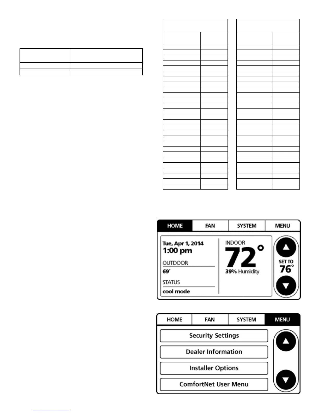
BOOST MODE is ON by default and is activated when the
outdoor temperature reaches 105°F. BOOST MODE can be
disabled and enabled and the activation temperature ad-
justed in the BOOST TEMP menu using the following proce-
dure:
1. On the CTK04 HOME screen, select MENU.
2. From the MENU screen, select COMFORTNET™ USER
MENU.
SUCTION PRESSURE LIQUID PRESSURE
PSIG PSIG
50 1 200 70
52 3 210 73
54 4 220 76
56 6 225 78
58 7 235 80
60 8 245 83
62 10 255 85
64 11 265 88
66 13 275 90
68 14 285 92
70 15 295 95
72 16 305 97
74 17 325 101
76 19 355 108
78 20 375 112
80 21 405 118
85 24 415 119
90 26 425 121
95 29 435 123
100 31 445 125
110 36 475 130
120 41 500 134
130 45 525 138
140 49 550 142
150 53 575 145
160 56 600 149
170 60 625 152
SATURATED SUCTION PRESSURE
TEMPERATURE CHART
SATURATED LIQUID PRESSURE
TEMPERATURE CHART
R-410A
°F
R-410A
°F

 Loading...