EasyManua.ls Logo

Amana PGA**C User Manual

Amana PGA**C
85 pages
To Next Page IconTo Next Page
Page #1 background imageLoading...
Page #1 background image
RS6300003 Rev. 1
January 2007
PHB**C, PHD**C PACKAGE HEAT PUMPS
PGA**C, PGB**C, PGD**C PACKAGE GAS
& PCC**C PACKAGE COOLERS
Service
Instructions
®
is a trademark of Maytag Corporation and is used under license
to Goodman Company, L.P. All rights reserved. Copyright © 1999-2007 Goodman Company, L.P.
This manual is to be used by qualified, professionally trained HVAC
technicians only. Goodman does not assume any responsibility for
property damage or personal injury due to improper service
procedures or services performed by an unqualified person.
Models listed on
Page 6

Table of Contents

Other manuals for Amana PGA**C

Question and Answer IconNeed help?

Do you have a question about the Amana PGA**C and is the answer not in the manual?

Amana PGA**C Specifications

General IconGeneral
BrandAmana
ModelPGA**C
CategoryAir Conditioner
LanguageEnglish

Summary

Service Instructions

IMPORTANT INFORMATION

Safe Refrigerant Handling Practices

Guidance on handling refrigerants safely to prevent hazards and comply with regulations.

PRODUCT IDENTIFICATION

Unit Identification Components

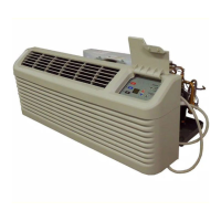
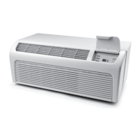
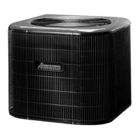
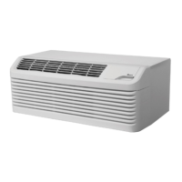
Details on how to identify unit models by type, family, series, capacity, voltage, and heating input.

Package Gas Unit Identification

Heat Pump and Cooler Identification

ACCESSORIES

Accessory Types and Applications

Overview of available accessories, their part numbers, and intended applications.

Thermostat Accessories

LIGHTING INSTRUCTIONS

Safety and Operating Precautions

Essential safety warnings and step-by-step instructions for lighting the appliance.

Gas Leak Detection and Response

Procedures to follow if a gas odor is detected, including immediate actions and emergency contacts.

PRODUCT DESIGN

Unit Dimensions and Clearances

Diagrams and specifications for unit installation clearances and overhangs.

PRODUCT DESIGN: Electrical Wiring Considerations

PRODUCT DESIGN: Gas Supply and Piping Requirements

SYSTEM OPERATION

System Operation: Cooling Cycle

Explanation of the refrigeration cycle for cooling, including refrigerant properties and component functions.

System Operation: Heating Cycle

Description of the heating cycle for heat pump and gas units, including reversing valve function.

SYSTEM OPERATION: Defrost Cycle Operation

SCHEDULED MAINTENANCE

Monthly Maintenance Checks

Tasks to perform monthly, including filter inspection and condensate line check.

Annual Maintenance Tasks

Procedures for qualified personnel, including coil cleaning and electrical connection inspection.

Testing and Performance Procedures

Essential test equipment for diagnosis and procedures for cooling/heating performance tests.

SERVICING

Cooling/Heat Pump Service Analysis Guide

Troubleshooting guide for cooling and heat pump system issues based on symptoms and possible causes.

Gas Heating Service Analysis Guide

Troubleshooting guide for gas heating system issues, identifying symptoms and potential causes.

SERVICING PROCEDURES: S-1 Checking Voltage

SERVICING PROCEDURES: S-3 Checking Thermostat, Wiring, and Anticipator

SERVICING PROCEDURES: S-7 Checking Contactor and S-15 Checking Capacitor

SERVICING PROCEDURES: S-15A Resistance Check, S-15B Capacitance Check, S-16 Checking Fan and Blower Motor

SERVICING PROCEDURES: S-16B ECM/ICM Motors and ECM/ICM Control Connections

SERVICING PROCEDURES: Replacing ICM Control Module

SERVICING PROCEDURES: S-16E Testing Interface Board

TROUBLESHOOTING ECM BLOWER MOTORS

ECM Motor Symptoms and Causes

Common symptoms of ECM motor issues, their possible causes, and corrective actions.

SERVICING PROCEDURES: S-17 Checking Compressor Windings

S-17A Resistance Test

Method for testing compressor winding resistance and checking internal overload status.

S-17B Ground Test

Procedure to check for electrical ground faults between compressor terminals and the unit housing.

SERVICING PROCEDURES: S-17D Operation Test and S-18 Testing Crankcase Heater

SERVICING PROCEDURES: S-21 Checking Reversing Valve and S-24 Testing Defrost Board

SERVICING PROCEDURES: Defrost Control Board Testing Methods

SERVICING PROCEDURES: S-50 Checking Heater Limit Controls and S-52 Checking Heater Elements

SERVICING PROCEDURES: S-53 Outdoor Temperature Control and S-100 Refrigeration Repair Practice

SERVICING PROCEDURES: S-102 Evacuation and S-103 Charging Procedures

SERVICING PROCEDURES: S-104 Compressor Efficiency

S-105 TXV Basics, S-106 Overfeeding, S-107 Underfeeding

Explanation of TXV function and checks for over/underfeeding issues.

SERVICING PROCEDURES: S-108 Superheat Check and Adjustment

Superheat Adjustment Information

Note that expansion valves are factory set and not field adjustable.

SERVICING PROCEDURES: S-109 Checking Subcooling

S-110 Checking Expansion Valve Operation

Method to check TXV operation by monitoring pressure changes when the bulb is heated or cooled.

SERVICING PROCEDURES: S-111 Fixed Orifice Devices and S-113 Overcharge/S-114 Non-Condensables

SERVICING PROCEDURES: S-200 Checking External Static Pressure

S-300 Testing Primary Limit Control

Instructions for testing the primary limit control, which is a fixed setting device.

SERVICING PROCEDURES: S-301 Testing Auxiliary Limit Control

S-302 Checking Flame Rollout Switch

Testing the flame rollout switch, wired in series with the primary limit and ignition control.

SERVICING PROCEDURES: S-304 Testing Gas Valve

Furnace Not Firing Servicing Procedure

Steps to take when the furnace fails to fire, including safety checks and reset procedures.

SERVICING PROCEDURES: Reset After Control Lockout

SERVICING PROCEDURES: S-306 Checking Orifices

S-307 Checking Gas Pressure

Guidelines for checking and adjusting gas inlet and manifold pressures for natural gas and propane.

SERVICING PROCEDURES: S-310 Checking Pressure Control

SERVICING PROCEDURES: Honeywell Smart Valve Sequence of Operation SV9500

SMART VALVE DIAGNOSTIC / TROUBLE SHOOTING CHART

Smart Valve System Checks and Actions

Diagnostic chart for Smart Valve systems, outlining checks and corrective actions for various components.

SERVICING PROCEDURES: S-311 High Altitude Application

S-313 Testing Ignition Control Module

Procedure for testing the ignition control module, including ground wire checks and polarity.

SERVICING PROCEDURES: Honeywell Smart Valve Ignition Systems Operation

DSI Direct Spark Ignition Systems Operation

Normal sequence of operation for DSI Direct Spark Ignition systems.

SERVICING PROCEDURES: Diagnostics Flash Codes

S-314 Checking Flame Sensor

Procedure for checking flame sensor operation and microamp signal for combustion proof.

SERVICING PROCEDURES: Honeywell Smart Valve Flame Sensor Testing

DSI Direct Spark Ignition Flame Sensor Testing

Procedure for testing DSI flame sensors by measuring microamp readings.

SERVICING PROCEDURES: S-315 Checking Hot Surface Igniter

WIRING DIAGRAMS

PGB24, 30, 36 & 42 Wiring Diagrams

Wiring diagram for PGB models 24, 30, 36, and 42, detailing component connections.

WIRING DIAGRAMS: PGD24, 30, 36, 42

WIRING DIAGRAMS: PHB42, 48, 60

WIRING DIAGRAMS: PHD24, 30, 36

WIRING DIAGRAMS: PHD42C02E

WIRING DIAGRAMS: PHD48, PHB60

WIRING DIAGRAMS: PCC24, 30, 36C02 [E/F]

WIRING DIAGRAMS: PCC42, 48C02 [E/F]

WIRING DIAGRAMS: PCC60C02 [E/F]

WIRING DIAGRAMS: PHB/PHD Wiring with ATK Control

WIRING DIAGRAMS: PHB/PHD Wiring with ATK Thermostat Input

WIRING DIAGRAMS: PHB/PHD Wiring with Freeze Protection

Related product manuals