EasyManua.ls Logo

Amana PTH153G35AXXX - User Manual

Amana PTH153G35AXXX
20 pages
Print Icon
To Next Page IconTo Next Page
Loading...
This manual must be left with the owner of the equipment.
PACKAGE TERMINAL
AIR CONDITIONER/HEAT PUMP
INSTALLATION INSTRUCTIONS & OWNERS MANUAL
Standard and Remote Applications with LED Control
IO-447B
03/2017
is a registered trademark of Maytag Corporation or its related companies and is used
under license to Goodman Company, L.P., Houston, TX, USA. All rights reserved.
ATTENTION INSTALLING PERSONNEL
As a professional installer you have an obligation to know the
product better than the customer. This includes all safety pre-
cautions and related items.
Prior to actual installation, thoroughly familiarize yourself with
this Instruction Manual. Pay special attention to all safety warn-
ings.
Often during installation or repair it is possible to place yourself
in a position which is more hazardous than when the unit is in
operation.
Remember, it is your responsibility to install the product safely
and to know it well enough to be able to instruct a customer in
its safe use.
Safety is a matter of common sense...a matter of thinking before
acting. Most dealers have a list of specific good safety
practices...follow them.
The precautions listed in this Installation Manual are intended as
supplemental to existing practices. However, if there is a direct
conflict between existing practices and the content of this manual,
the precautions listed here take precedence.
5151 San Felipe, Suite 500Houston, TX 77056 • www.amana-ptac.com
© 2014 - 2015, 2017 Goodman Company, L.P.
Question and Answer IconNeed help?

Do you have a question about the Amana PTH153G35AXXX and is the answer not in the manual?

Summary

ATTENTION INSTALLING PERSONNEL

ENERGY MANAGEMENT SYSTEM FEATURES

INSTALLATION INSTRUCTIONS

WIRING AND ELECTRICAL CONNECTIONS

Power Cord Requirements and Safety Precautions

Specific wiring requirements for different voltage units and power cord safety.

OPERATING INSTRUCTIONS AND CONTROLS

User Controls and Thermostat Setting

How to use the 7-button touch pad and adjust temperature settings.

VENT CONTROL AND AIRFLOW ADJUSTMENTS

Remote Thermostat Operation Setup

How to configure the unit for operation with a remote thermostat.

MAINTENANCE AND CLEANING PROCEDURES

Intake Air Filter Cleaning and Removal

Importance and procedure for monthly cleaning of intake air filters.

OPERATIONAL CHECKS AND CONFIGURATION

Configuration Settings Entry Procedure

Introduces configuration settings and how to enter the feature mode.

DIAGNOSTIC MAINTENANCE AND STATUS REPORT

Entering Diagnostic Status Report Mode

Steps to access the diagnostic status report and view information.

Viewing Operating Temperatures and Past Failures

Instructions to check current temperatures and review the historical failure log.

DIAGNOSTIC CODES AND ERROR DEFINITIONS

Failure, Airflow, and Refrigeration Alerts

Details codes for unit failures, airflow issues, and refrigeration alerts.

Overview

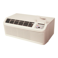
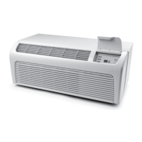
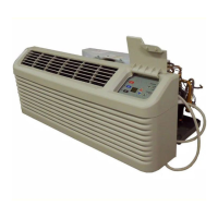
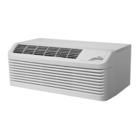
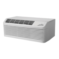
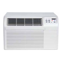
This document serves as both an installation instruction manual and an owner's manual for a Package Terminal Air Conditioner/Heat Pump (PTAC) unit, specifically designed for standard and remote applications with an LED control. The unit is proudly assembled in the USA and boasts over 40 years of manufacturing experience.

Function Description

The PTAC unit is a versatile heating and air conditioning system designed for through-the-wall installation in new or existing buildings. It functions as both an air conditioner and a heat pump, providing cooling and heating capabilities for a room. The unit is equipped with an LED control panel for easy operation and can also be integrated with remote thermostats and energy management systems for enhanced control and efficiency.

Usage Features

The PTAC unit offers several features to optimize comfort and energy efficiency:

  • 7-Button Touch Pad with Display: The primary control interface is a touch pad located behind the control door. It allows users to select temperature, operation mode (HEAT, COOL, OFF), and fan speed (HIGH, LOW, AUTO). The display provides visual feedback on settings and operational status.
  • Automatic 3-Minute Compressor Lockout: To protect the compressor, the unit prevents it from restarting for three minutes after it cycles off.
  • Automatic 2nd Stage Electric Heat: If the room temperature drops 4°F below the set point in heating mode, the reverse cycle heat is automatically shut off, and electric strip heat is engaged to provide additional warmth.
  • Automatic Freeze Protection: When power is supplied and the master switch is ON, the unit activates freeze protection. If the temperature drops below 40°F, the fan motor and electric strip heat turn on to prevent freezing. This feature can be disabled if not needed.
  • Random Restart Delay: To mitigate power surges after an outage, the unit incorporates a two to four-minute random restart delay. This can be bypassed by setting the mode switch to "fan only" or "off" before applying power.
  • Load Shedding: The unit can be configured for load shedding operations. When a switch is closed between designated input terminals, the compressor and electric heater will lock out until the switch is opened, allowing for energy management.
  • Transfer Fan: A daughter board allows for the connection of an external (transfer) fan, requiring a user-supplied relay and potentially an external transformer kit.
  • Vent Control: For standard PTAC models, a vent control allows outside air to be drawn into the conditioned area, providing ventilation. This feature can increase heating or cooling loads and operating costs. The vent door should be closed in hydronic heat installations when outdoor temperatures are below freezing to prevent coil damage.
  • Air Discharge Grille: The discharge grille can be adjusted to expel air at either a 16° or 56° angle, allowing for directional airflow control.
  • Remote Thermostat Compatibility: The unit is designed to operate with manufacturer-approved remote wall-mounted thermostats. Once configured for remote mode, the control touchpad will only accept configuration and diagnostics inputs, with the room occupant operating the unit via the remote thermostat.
  • Front Desk Control (IN1, IN2, COM): The unit can be integrated with a front desk switch. Shorting across these terminals disables unit operation, with freeze protection remaining active. This feature is useful for unrented setback energy management, displaying "Fd" on the display when active.
  • Energy Management System Features:
    • Temperature Setback: This option automatically adjusts operational temperatures for unrented or unoccupied rooms, saving energy. This mode is configured through the unit's settings.
    • Door Switch and Motion Sensor Low Voltage Terminals (IN1, IN2, COM): These terminals allow for wired connection of a door sensor to the control board. The motion sensor interprets door movement as occupancy. If no door activity is detected for thirty minutes, energy management temperature setback activates.
    • Serial Port Interfaces: A serial port on the control board facilitates two-way communication with an optional RF antenna for wireless communication.
  • Diagnostic Light: A green diagnostic light on the touchpad indicates operational warnings, often signaling that the filter or coils need cleaning.

Maintenance Features

Regular maintenance is crucial for the safe and efficient operation of the PTAC unit:

  • Intake Air Filters: The durable polypropylene intake air filters should be cleaned monthly, or more frequently in dusty environments. To clean, turn the unit OFF, grasp each filter by its molded handle, pull it straight up, and clean with a vacuum or running water.
  • Vent Screen: Before cleaning the vent screen, disconnect power to the unit. Remove the cabinet front, slide the chassis out of the wall sleeve, clean the vent screen, and then reassemble. If the unit operates with the vent door closed, cleaning the vent screen is not necessary.
  • Cabinet Front and Discharge Air Grille: These can be cleaned with a water-dampened cloth. Avoid hydrocarbon-based or ammonia-based cleaners, as they can damage the surfaces.
  • Yearly Maintenance and Cleaning: To maintain top performance, establish an annual cleaning/inspection schedule. This involves removing the unit from the sleeve and thoroughly cleaning and rinsing the evaporator coils, condenser coils, basepan, and drain passages. Use a mild biodegradable detergent like Simple Green™. Protect the control board and electrical components from water. Avoid harsh or caustic cleaning agents, bleach, or coil cleaners not designed for PTAC products, as they can damage aluminum fins or coil material and may create a fire hazard, voiding the warranty.
  • Basepan and Condenser Coil Cleaning: Before cleaning, turn OFF the unit and disconnect power. Create a watertight seal over the control panel and fan motor with plastic. Spray the condenser coil and basepan with water, then a mild biodegradable detergent, let it sit for five minutes, and rinse again with water (no higher than ordinary garden hose pressure or 120°F). Tilt the non-compressor side of the unit up to 45 degrees to drain water, then wipe the basepan dry. Reinstall the unit and allow it to dry for 24 hours before reapplying power.
  • Wall Sleeve: Clean the wall sleeve when cleaning the unit. Check and seal any potential air and water openings around the sleeve. Recheck the sleeve's level, ensuring a slight downward pitch from the indoor to the outdoor side (1/4 bubble tilt to the outside) and level from right to left.
  • Algaecide Application: Place a non-acidic algaecide in the basepan to inhibit bacteria growth, ensuring it is compatible with wet coil operation and non-corrosive to the coil.
  • Clearance Check: Regularly check that the intake and discharge air paths are not blocked. Maintain a minimum of eight inches clearance from furniture, beds, or other objects. Restricted airflow can reduce performance and damage components.
  • Diagnostic Maintenance & Status Report: The unit provides detailed information on its operation, including present modes, failures, airflow restriction warnings, operating temperatures, and past failures. This report can be accessed by pressing and holding the up and down arrows, then quickly pressing the COOL key twice. This helps identify issues like dirty filters or coils, and active or past failure codes.

Amana PTH153G35AXXX Specifications

General IconGeneral
Voltage208/230 V
HSPF8.0
Cooling Capacity15, 000 BTU
Dimensions42 x 15 x 14.5 inches
TypePackaged Terminal Heat Pump

Related product manuals