Do you have a question about the Amana PTH073J35A and is the answer not in the manual?
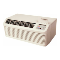
The device is a Package Terminal Air Conditioner/Heat Pump (PTAC) designed for through-the-wall installation in new or existing buildings. It functions as both an air conditioner and a heat pump, providing heating and cooling capabilities. The unit is controlled via a 7-button touch pad with a display, located behind a control door on the front of the unit. It also supports remote control options through a wired wall-mounted thermostat or wireless RF antenna.
The PTAC unit provides heating and cooling for a room. In cooling mode, it lowers the room temperature, while in heating mode, it maintains a selected room temperature by cycling between heat pump operation and electric strip heat. The unit is equipped with an automatic 3-minute compressor lockout, preventing rapid cycling. It also features automatic 2nd stage electric heat, which activates if the room temperature falls 4°F below the set point, and automatic freeze protection, which turns on the fan motor and electric strip heat if the unit senses temperatures below 40°F.
For power surge protection after an outage, the unit includes a two to four minute random restart delay. This delay can be bypassed by setting the mode switch to "fan only" or "off" before applying power. On 265-volt units, factory-installed fuse holders are present behind the front panel, and a blown fuse should be checked if the unit is not operating.
The unit supports load shedding operations when configured, allowing the compressor and electric heater to lock out if a switch is closed between designated input terminals (IN1 and COM or IN2 and COM). A PTAC Wire Harness Kit (PWHK01G70) is required for this feature. Additionally, a daughter board allows for an external (transfer) fan connection, requiring a user-supplied relay and potentially an external transformer kit.
Energy Management System (EMS) features are available, including temperature setback for unrented or unoccupied rooms. This mode automatically adjusts operational temperatures and is configured through the unit's settings. Door switch and motion sensor low voltage terminals (IN1, IN2, COM) allow for wired connections to a door sensor, which signals occupancy. If no door activity is detected for thirty minutes, the EMS temperature setback activates. A serial port on the control board facilitates two-way communication with an optional RF antenna for wireless control.
The 7-button touch pad allows users to control temperature and operation mode. Pressing the COOL or HEAT thermostat controls along with the up or down arrows adjusts the desired room temperature. The fan speed can be set to high, low, or auto. In AUTO mode, the fan speed adjusts automatically between low and high depending on the selected HEAT or COOL mode.
For 230/208V and 115V units, LCDI or AFCI power cords are included, which sense current leakage and can open the electrical circuit. If the unit does not operate, users should check the reset button on the power cord.
A green diagnostic light on the touchpad indicates operation warnings, typically signaling that the filter or coils need cleaning. If the light remains on after cleaning, users can refer to the Diagnostic & Status Report section for further assistance.
Remote control inputs (C, R, GL, W2, Y/W1, B/O, and GH terminals) are provided for a manufacturer-approved remote wall-mounted thermostat. The unit can be configured to operate solely via the remote thermostat, bypassing the control touchpad for most functions. The PTAC Wire Harness Kit is required for these remote thermostat options.
The unit also features a vent control, allowing outside air to be drawn into the conditioned area for ventilation. This control is accessed by removing the cabinet front and rotating a lever. For hydronic heat installations, the vent door must be kept closed in freezing outdoor temperatures to prevent coil freezing. The air discharge grille can be adjusted to expel air at either a 16° or 56° angle by removing the cabinet front and rotating the grille.
Regular maintenance is crucial for the PTAC unit's operational performance and efficiency. The intake air filters, made of durable polypropylene, should be cleaned monthly or more often in dusty conditions. To clean, users should turn off the unit, grasp each filter by its molded handle, pull it straight up, and clean it with a vacuum or running water.
The vent screen should also be cleaned by disconnecting power, removing the cabinet front, sliding the chassis out of the wall sleeve, and then cleaning the screen. The cabinet front and discharge air grille can be cleaned with a water-dampened cloth, avoiding hydrocarbon-based or ammonia-based cleaners.
Yearly maintenance involves a thorough cleaning and inspection of the unit, including evaporator coils, condenser coils, basepan, and drain passages. This requires removing the unit from its sleeve. A mild biodegradable detergent like Simple Green™ is recommended, with care taken to protect electrical components from water. Harsh or caustic cleaners should be avoided as they can damage aluminum fins or coil material.
For basepan and condenser coil cleaning, the unit's mode switch should be turned OFF, and power disconnected. A water-tight seal should be created over the control panel and fan motor before spraying down the condenser coil and basepan with water and a mild biodegradable detergent. After five minutes, the coil and basepan should be rinsed with water (no higher than 120°F). The unit should then be tilted to drain excess water, wiped dry, and allowed to dry for 24 hours before reapplying power. A non-acidic algaecide can be placed in the basepan to inhibit bacteria growth.
Clearances around the unit, including intake and discharge air paths, should be checked regularly to ensure they are not blocked or restricted. A minimum of eight inches clearance from furniture or other objects is needed to prevent reduced operational performance and potential damage to components.
The Diagnostic Maintenance & Status Report mode provides detailed information on control operation, status, failures, airflow restrictions, operating temperatures, and past failures. This mode is accessed by pressing and holding the up and down arrows, then quickly pressing the COOL key twice. It displays active failures, operating temperatures (set point, wireless thermostat, indoor ambient, indoor coil, indoor discharge air, outdoor coil, outdoor ambient, and spare probe temperatures), and a log of the last 10 failure codes. This information helps in troubleshooting and determining if professional servicing is required.
| HSPF | 8.2 |
|---|---|
| Voltage | 208/230 V |
| Refrigerant Type | R-410A |
| Phase | 1 |
| Sound Level (Outdoor Unit) | 54 dB |