Do you have a question about the Amana RCB and is the answer not in the manual?
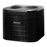
Discusses RCA, RCB, RCC, VCB, and RCE models, air discharge, refrigerant connections, and compressor characteristics.
Details Amana coils and BBA/BBC blower cabinets, including variable speed motors and usage.
Explains the process of cooling and dehumidification of air through the evaporator coil.
Describes how heating is activated using thermostats and electric heaters, including time delay relays.
Explains the control board logic for BBA/BBC models, including LED indicators and operational sequences.
Details procedures for testing unit performance and acceptable deviation ranges.
Outlines monthly checks for return filters and condensate lines for optimal system operation.
Covers annual checks of coils, casings, wiring, and refrigerant leaks by qualified personnel.
Lists essential tools for diagnosis, including meters for voltage, amperage, temperature, and pressure.
Explains how to conduct a cooling performance test to diagnose faults and apply results to a guide.
Guides on measuring voltage at the condensing unit and compressor terminals for proper operation.
Instructions for visually inspecting wiring for damage and checking continuity with an ohmmeter.
Steps to verify thermostat operation and wire integrity for proper heating and cooling control.
Details on testing time delay relays used in blower cabinets and electric heaters for efficient sequencing.
Explains how to test compressor contactors and fan relays for proper operation by checking coil and contacts.
Guides on testing the high pressure control that opens contacts to protect the compressor from overloads.
Instructions for testing the low pressure control that opens contacts on a drop in pressure for compressor protection.
Procedures for checking run and start capacitors, including resistance and capacitance tests.
Details on testing motor windings for continuity and ground faults to ensure proper operation.
Guides on testing compressor windings for continuity, shorts, grounds, and potential hazards.
Outlines safe procedures for handling refrigerant, including evacuation and charging.
Methods for detecting refrigerant leaks using halide or electronic leak detectors.
Details the importance of system evacuation for efficiency and preventing corrosive acid formation.
Provides instructions for correctly charging the system with the specified amount of refrigerant.
Explains the function and control of the expansion valve based on temperature and pressure.
Details the function and troubleshooting for capillary tube metering devices.
Explains how to identify and correct an overcharged refrigerant condition.
Provides information on acceptable static pressure levels for proper system airflow and performance.
Guides on measuring static pressure in return and supply ducts for determining airflow.
Illustrates the electrical connections for the blower delay kit installed in the furnace.
Provides wiring diagrams for various condensing unit models, detailing field and factory connections.
Illustrates wiring diagrams for RCA/B condensing units, showing electrical connections for various configurations.
Shows wiring diagrams for VCA and RCB condensing units, detailing electrical connections and components.
Wiring diagrams for BHA and BCA blower coil units, detailing connections for various configurations.
Wiring diagrams for EHK-A heater kits with BHA-FA or BCA-TA units, showing electrical connections.
Wiring diagrams for EHK-A heater kits with BHA-FA or BCA-TA units, detailing electrical connections.
Wiring diagrams for EHK-A heater kits with BHA-FA or BCA-TA units, illustrating electrical connections.
Wiring diagrams for BBA24-60A2A models, showing electrical connections for the control and blower motor.
Wiring diagrams for BBC36-48-60A2A models, detailing control board and interface board connections.
| Brand | Amana |
|---|---|
| Model | RCB |
| Category | Air Conditioner |
| Language | English |