21
Component Testing Procedures
!
WARNI NG
To avoid risk of electrical shock, personal injury or death, disconnect power to oven and discharge capacitor
before servicing, unless testing requires it.
Electronic Control Panel
Service Test Mode: Open door, Press and Hold pad 3 for 5
seconds to enter service test mode.
Press Pad 1..................................................
Press Pad 2..................................................
Press Pad 3..................................................
Press Pad 4..................................................
Press Pad 5..................................................
Press Pad 6..................................................
Press Pad 7..................................................
Press Pad 8..................................................
Press Pad 9..................................................
Press Pad 0..................................................
Stop/Reset Pad ............................................
SERVICE appears in the display
Indicates number of hours
magnetron has been turned on
Indicates number of times
magnetron tube has been turned
on and off
Indicates number of door cycles
CLEAR (Press START pad to
reset service data.)
Indicates amperage (Top Mag)
Indicates amperage (Bottom Mag)
RESET (Clear Service Alarm)
N/A
N/A
N/A
Exit Service Test Mode
Error codes: E-08..............................................................
E-09..............................................................
E-10..............................................................
Replace Control Board
Replace Control Board
Shorted or Open Keypad – Test
and replace if necessary
stluseR gnitseT tnenopmoC noitartsullI
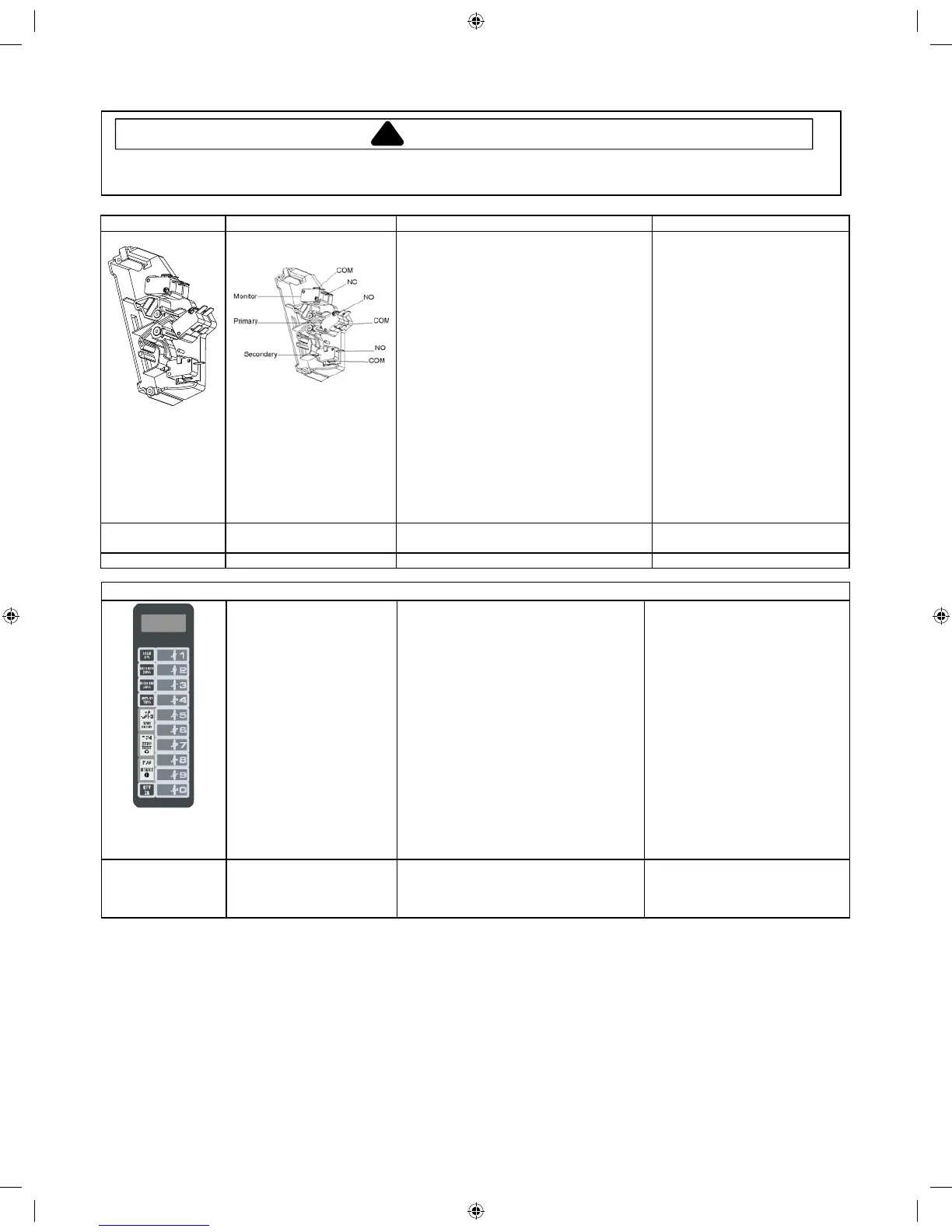
Interlock switch assembly
Disconnect wires to switch.
With door open measure resistance from:
Top Monitor – COM (PK) – NO (BL) ........
Btm Monitor – COM (WH) – NO (RD) ......
Top Primary – COM (RD BK) – NC (BN)
Btm Primary – COM (BK) – NC (BL) ........
Secondary – COM (PK) – NC (GN) ........
With door closed measure resistance from:
Top Monitor – COM (PK) – NO (BL) .......
Btm Monitor – COM (WH) – NO (RD) ......
Top Primary – COM (RD BK) – NC (BN)
Btm Primary – COM (BK) – NC (BL) ........
Secondary – COM (PK) – NC (GN) ........
After verifying or replacing the
module, reconnect wires to switch
and check operation of monitor circuit
before operating the oven.
Indicates continuity
Indicates continuit
y
Infinite
:
Infinite
:
Infinite
:
Infinite
:
Infinite
:
Indicates continuity
Indicates continuity
Indicates continuity
Lamp receptacle Test continuity of receptacle terminals. Indicates continuity with bulb
installed.
Wire Harness Test continuity ytiunitnoc setacidnI seriw fo
2011 RFS Training Manual.indd 21 10/3/2011 8:36:46 AM
 Loading...