23
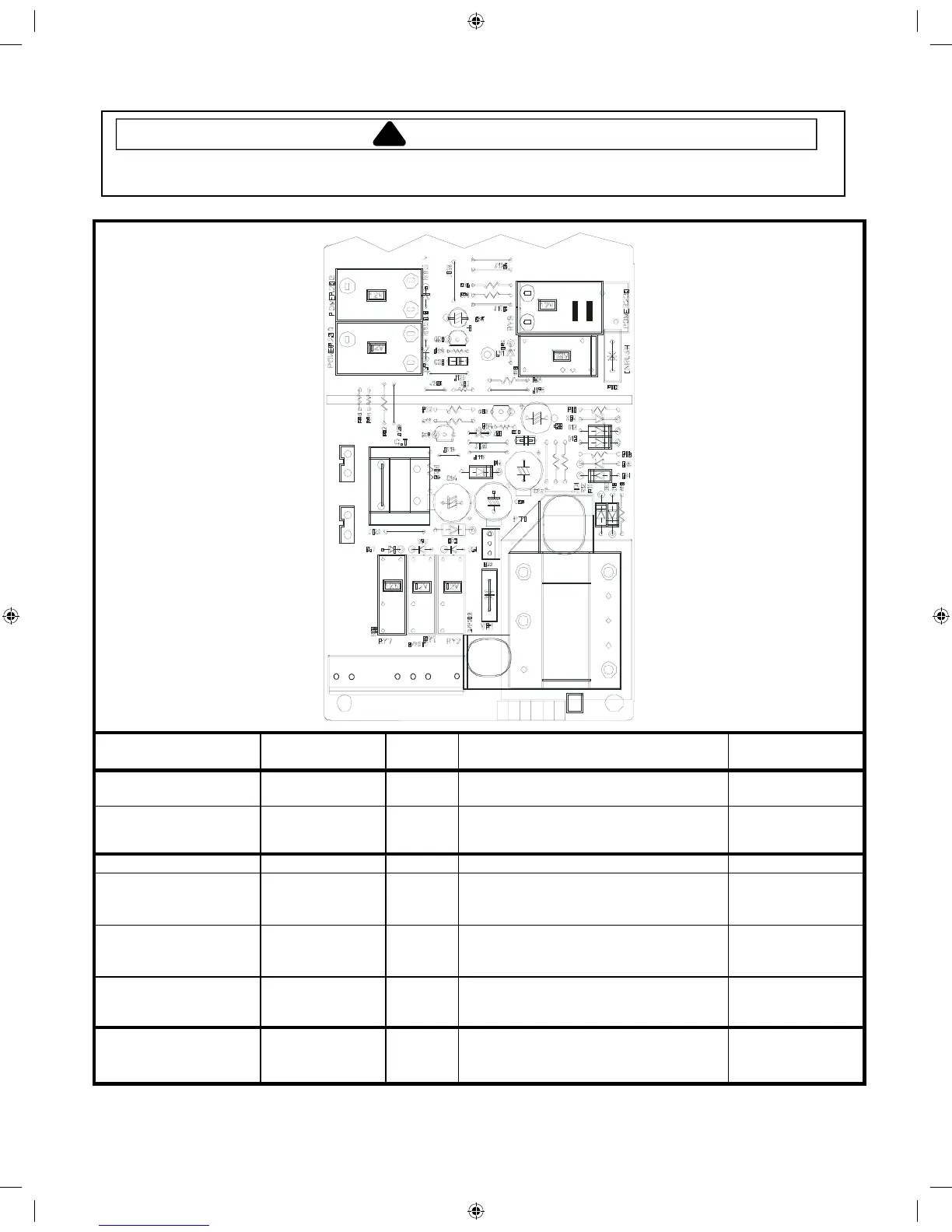
Component Testing Procedures RFS18*
!
WARNI NG
To avoid risk of electrical shock, personal injury or death, disconnect power to oven and discharge capacitor
before servicing, unless testing requires it.
TAB 1
TAB 2
RLY 3
19
3
54
8
C1N
12
Function Test Set-Up /
Condition
Meter
Setting
Probe Placement Results
Power to current
transformer
All Conditions Volts Tab 1 to CN1 Pin 3 208 / 240 VAC
Power from current
transformer
All Conditions Volts Tab 2 to CN1 Pin 3 208 / 240 VAC
Power from Oven TCO All Conditions Volts CN1 – Pin 1 (Black wire to ground) 208 / 240 VAC
Power to Oven Light Standby .............
Ready................
Cook..................
Volts
Volts
Volts
CN1 – Pin 4 to Pin 1 .............................
CN1 – Pin 4 to Pin 1 .............................
CN1 – Pin 4 to Pin 1 .............................
208 / 240 VAC
0 VAC
0 VAC
Power to Blower Motor Standby .............
Ready................
Cook..................
Volts
Volts
Volts
CN1 – Pin 5 to Pin 1 .............................
CN1 – Pin 5 to Pin 1 .............................
CN1 – Pin 5 to Pin 1 .............................
208 / 240 VAC
0 VAC
0 VAC
Secondary Interlock
Switch
Door Closed ......
Door Opened ....
Ohms
Ohms
CN1 – Pin 8 to Pin 9 .............................
CN1 – Pin 8 to Pin 9 .............................
Continuity
Infinite
Power to Relay 3 Standby .............
Ready................
Cook..................
Volts
Volts
Volts
Relay 3 – Pin 1 to Pin 2 ........................
Relay 3 – Pin 1 to Pin 2 ........................
Relay 3 – Pin 1 to Pin 2 ........................
208 / 240 VAC
208 / 240 VAC
0 VAC
2011 RFS Training Manual.indd 23 10/3/2011 8:36:47 AM
 Loading...