12
ELECTRIC HEAT STAGING USING GY42 AT BLOWER CONNECTOR
Heater KW from KW from Total
Kit W2 GY42 KW
EHK05A 4.8 0 4.8
EHK07A 4.8 2.4 7.2
EHK10A 4.8 4.8 9.6
EHK15A 4.8 9.6 14.4
EHK20A 9.6 9.6 19.2
EHK25A 14.4 9.6 24.0
EHK30A 19.2 9.6 28.8
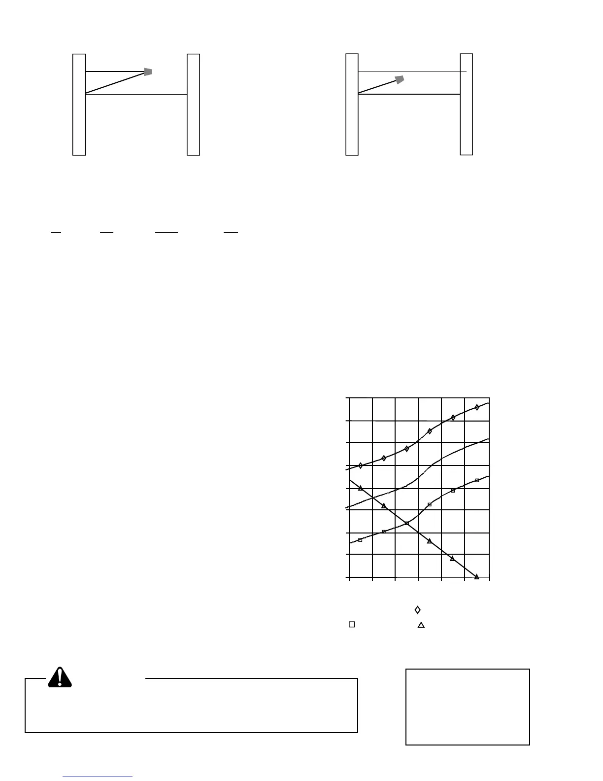
Use Manual J or Right-J or equivalent to calculate the
building heating and cooling loads at design conditions.
Select the system size (in tons) to meet the cooling load.
Add enough electric heat to meet the heating load. Use
data from the unit “Specification Sheet” to plot a graph of
system capacities and building load vs. outdoor tempera-
ture. Examine the graph and the table above. Set the
outdoor thermostat accordingly.
EXAMPLE: A home in Nashville, TN needs three tons of
cooling. Its heating load has been calculated as 40600
BTUH at 14°F outdoor temperature. An RHA36A2A and
BHA36FA002A will be used.
As the graph shows, 9.6KW (EHK10A) must be added to
the BHA36 to meet the heating load. As the chart above
shows, the EHK10A can be split, with 4.8KW from W2 and
4.8KW through the outdoor thermostat to GY42. The “Unit
+ 4.8KW” will just meet the “Bldg. Load” at an outdoor
temperature of 20°F. It is usually desirable to provide a
small amount of extra capacity. Therefore, for this instal-
lation, the outdoor thermostat ATK05 should be set at
25°F.
This example is for purposes of illustration only. Actual
selection and application of equipment remains the sole
responsibility of the installer.
If an outdoor thermostat, not controlling the first group of
electric heaters, is to be used:
1. Disconnect power.
2. Remove and save wire nut shown above.
3. Extend GY42 wire into the low voltage terminal area.
4. Connect the GY42 wire as shown on the wiring sche-
matic for your system.
5. Wire nut and tape the unused GY41 wire to prevent
shorts.
PRELIMINARY HEATING PERFORMANCE
COLOR CODE
1ST GROUP COLOR
2ND GROUP NUMBER
OR-ORANGE BK-BLACK
YL-YELLOW BU-BLUE
VT-VIOLET RD-RED
BR-BROWN TN-TAN
GN-GREEN GY-GRAY
WARNING
To avoid personal injury, shock or death, disconnect the
electrical power before electrically connecting any
equipment or changing any existing wiring.
As shipped, connector in blower coil is as shown above.
5 4 2 6 3 9 8 7 1
W2
TERM. STRIP
GY42
GY41
GY41
W2
TERM. STRIP
GY42
GY41
GY41
5 4 2 6 3 9 8 7 1
10
50
30
70
+ UNIT + 4.8KW UNIT + 9.6KW
OUTDOOR TEMP (°F)
UNIT ALONE BLDG. LOAD
10
0
20
30
40
50
60
70
80
RHA36A2A
w/ BHA36F002A
BTUH
(Thousands)
+
+
+
+
+
+
+
 Loading...