32
EN
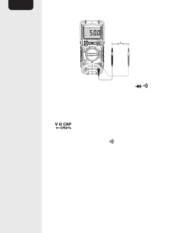
• Set the function switch (E) to the Ω CAP
position.
• Insert the black connector lead (Q) into the
COM input jack (L).
• Insert the red connector lead (Q) into the
input jack (K).
• Press the MODE button twice to switch to
continuity check mode. (10) should light up
on the display(A).
• Touch the test probes (Q) across the circuit or
part under test.
• The stabilized value on the display (A) is read as
the actual reading.
• If the resistance is less than approximately
50Ω, an audible signal is emitted.