6
11. INTERLOCK SYSTEM
INTERLOCK MECHANISM
The door lock mechanism has been specially
designed to eliminate completely microwave
activity when the door is opened during
cooking and thus to prevent the danger
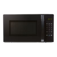
MOUNTING OF THE PRIMARY/MONITOR/
SECONDARY SWITCHES TO THE L ATCH BOARD
ADJUSTMENT
DIRECTION
PRIMARY
SWITCH
MONITOR
SWITCH
SECONDARY
SWITCH
INSTALLATION AND ADJUSTMENT OF THE
LATCH BOARD TO THE OVEN ASSEMBLY
• Adjust the latch board in the arrow direction so
that oven door will not have any play in it when
• Check for play in the door by pushing
the door release button. Door movement
should be less than 0.5 mm (1/64 in).
Don’t push the door release button while
making adjustments
latch moves smoothly after adjustments are
sure the primary, monitor, and secondary
switches operate properly by following the
CAUTION: CHECK THE CORRECT POSITION
MAGNETRON
H.V. TRANSFORMER
PRIMARY
H.V. CAP ACITOR
H.V.
DIODE
FIG. 1
H.V.FUSE
INTERLOCK CONTINUITY TEST
WARNING: FOR CONTINUED PROTECTION AGAINST
EXCESSIVE RADIATION EMISSION, REPLACE ONLY WITH
IDENTICAL REPLACEMENT PARTS.
1. PRIMARY INTERLOCK
SWITCH TEST
When the door release button is depressed
slowly with the door closed, an audible click
should be heard at the same time or successively
the latches should activate the switches with an
audible click
If the latches do not activate the switches
when the door is closed, the switches should
be adjusted in accordance with the adjustment
to the common (COM) and normally open (NO)
When the door is closed, the meter should
When the primary switch operation is abnormal,
make the necessary adjustment or replace the
2. SECONDARY INTERLOCK
SWITCH TEST
Disconnect the wire lead from the
Connect the ohmmeter leads to the common
(COM) and normally open (NO) terminals of the
n open circuit
closed, the
When the secondary switch operation is
abnormal, make the necessary adjustment or
replace the switch only with the same type of
3. MONITOR SWITCH TEST
Disconnect the wire lead from the monitor
common (COM) and normally closed (NC)
When the door is closed, meter should indicate
operation is abnormal, replace with the same
NOTE: After repairing the door or the
interlock system, it is necessary to do
this continuity test before operating
the oven.
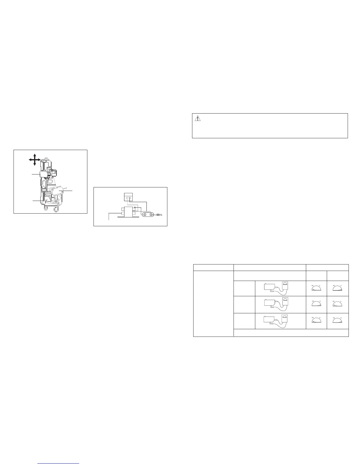
COMPONENTS TEST PROCEDURE
RESULTS
rooDrooD SEHCTIWS
edsolcnepo)devomer sdael eriW(
Primary
Switch
Monitor
Switch
NOTE : After checking for the continuity of switches, make sure that they are
correctly connected.
COM
NO
COM
NC
COM
NO
Secondary
Switch
Type No. KW3A
HK-14,
LF-10-02M(022M)
Type No. KW3A
HK-14,
LF-10-02M(022M)
Type No. KW3A
HK-14,
LF-10-02M(022M)
Check for continuity of the
switch with an Ohmmeter
 Loading...