8
FUS E
Check for continuity of the fuse with a
multi-meter.
NOTE: If the fuse is blown, check the primary, the secondary, and the monitor switches,
H.V.D. and H.V.C. before replacing the fuse.
If the fuse is blown by improper switch operation replace the defective switch and the
fuse at the same time. Replace just the fuse if the switches operate normally.
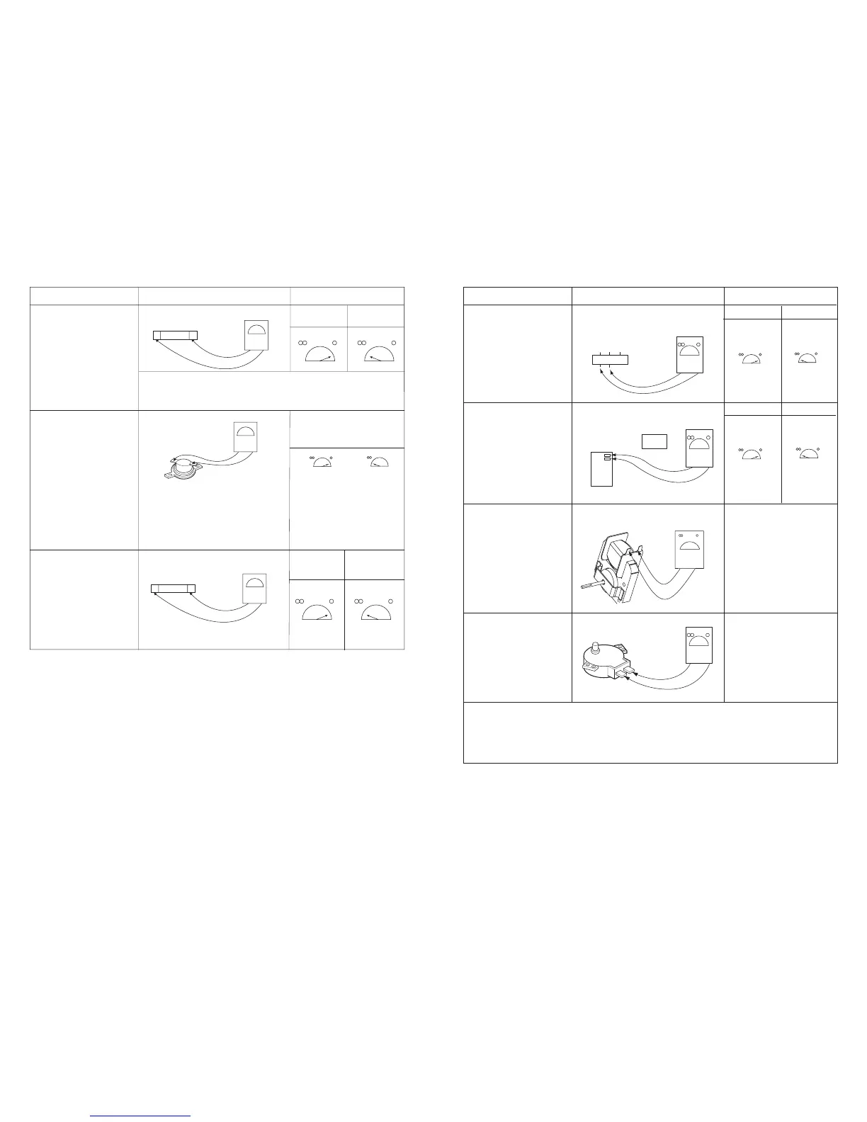
Normal Abnormal
COMPONENTS TEST PROCEDURE RESULTS
Below specified
temperature
Above specified
temperature
THERMAL CUT-OUT
H.V. FUSE
Normal Abnormal
FAN MOTOR
(Wire leads removed)
TURNTABLE
MOTOR
(Wire leads removed)
Measure the resistance.
(Ohmmeter scale: R x 1000)
NOTE: • A MICROWAVE LEAKAGE TEST MUST ALWAYS BE PERFORMED WHEN THE UNIT IS
SERVICED FOR ANY REASON.
• MAKE SURE THE WIRE LEADS ARE IN THE CORRECT POSITION.
• WHEN REMOVING THE WIRE LEADS FROM THE PARTS, BE SURE TO GRASP THE
CONNECTOR, NOT THE WIRES.
135
Measure the resistance.
(Ohmmeter scale: R x 1)
Normal:
Abnormal: Infinite or several Ω
00~5001
RELAY 1 OF PCB
(Wire leads removed)
NOTE: Relay
Relay 1: Fan motor
Turntable motor
Oven lamp
Microwave
Relay 1
Relay 1
Cooking Start OFF
Ω
Normal: Approx.100~200K
Abnormal: Infinite or several Ω
Ω
L.V.Transformer of PCB
(Refer to schematic diagram)
Check for PCB connector.
NOTE: Disconnect the 3 pin
connector from PCB.
Normal
Abnormal
COMPONENTS RESULTSTEST PROCEDURE
 Loading...