EasyManua.ls Logo

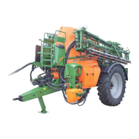
Amazone UG 3000 Nova User Manual

Amazone UG 3000 Nova
188 pages
To Next Page IconTo Next Page
Page #1 background imageLoading...
Page #1 background image
Instruction Manual
Trailed Sprayer
$0$=21(8*
UG 2200 Nova
UG 3000 Nova
UG 4500 Nova
MG 743
SB 236.1 (GB) 12. 2002
Printed in Germany
GB
!
Before starting opera-
tion carefully read and ad-
here to this instruction
manual and the safety ad-
vice.

Table of Contents

Question and Answer IconNeed help?

Do you have a question about the Amazone UG 3000 Nova and is the answer not in the manual?

Amazone UG 3000 Nova Specifications

General IconGeneral
BrandAmazone
ModelUG 3000 Nova
CategoryPaint Sprayer
LanguageEnglish

Summary

1 Details about the machine

1.2 Attention when using specific crop protection agents

Advises on potential damage from specific agents and handling precautions.

2. Safety

2.1 Danger when not adhering to the safety advice

Outlines risks of not following safety advice, including personal and environmental danger.

2.2 Qualification of operator

Specifies that only trained and informed persons may operate or repair the implement.

2.4 "Attention" pictographs and "advice" pictographs on the machine

Describes pictographs on the machine indicating dangerous points and advice.

2.5 Safety conscious operation

2.6 Safety advice for the operator

Provides essential safety advice for the operator.

2.6.1 General safety and accident prevention advice

Provides basic principles and numbered safety advice for safe machine operation.

2.6.4 Operating with PTO shafts

Safety instructions for the proper use and maintenance of PTO shafts.

2.6.5 Brakes

2.6.6 Hydraulic system

2.6.9 General safety and accident prevention advice for maintenance, repair and cleaning

2.6.10 Basic safety rules on crop protection equipment

3.1.1 Liquid flow- 1 pump

3.2.1 Liquid flow – 2 pumps

3.3.1 Control unit "NG"

3.3.2 Control unit "TG"

3.4.1.1 Switch box SKS 500/700/900

3.4.2 Switch box SKS 501/701/901

3.4.3 Switch box SKS 502/702/902

3.8 Filter equipment

3.8.2 Self cleaning the pressure filter of the control unit

3.10.2 Induction bowl with can wash

4. On receipt of the machine

4.1 First fitting of the switch box

Step-by-step guide for initially fitting the switch box and its components.

4.1.3 Switch box

4.2 PTO-shaft

4.2.1 Initial fitting and matching up of the PTO shaft

4.3 Setting the track

4.4 Matching the steering geometry for track following- or universal draw bar to the tractor

5. Hitching or unhitching the trailed sprayer

5.1.1 Attaching and Detaching

Step-by-step guide for attaching and detaching various draw bar types.

5.2 Dual circuit air brake system

5.3 Hydraulic brake system with parking brake

5.6 Electric switch box

6. En route to the field – Transport on public roads and ways

6.2 Running gear with two-circuit air brake system or hydraulic brake system

7. Putting into operation

7.2 Preparing the spray mixture

7.3 Calculating the filling or refilling quantities

7.3.1 Filling with water

7.3.2 Inducting spray agents

7.3.2.1 Liquid agents

7.3.2.2 Flushing of spray agent containers with the aid of the can wash nozzle

7.4 Setting the equal pressure control chest before the first operation and after any change of nozzles (only for "NG"-control unit)

7.5 Spraying crop protection liquid

7.5.3 Measures to avoid spray drift

7.5.4 Setting the spray rate [l/ha]

7.5.4.1 Determine the spray pressure

Steps to determine the correct spraying pressure based on nozzle type and rate.

7.5.4.2 Set the spray pressure

7.6 Calibrating

7.6.1 Determining the liquid rate [l/ha]

Method for determining liquid rate by driving a measured distance.

7.6.1.1 Determined by driving a measured distance

Detailed steps for measuring liquid rate via distance calibration.

7.6.1.2 Stationary calibrating from single nozzle output

7.7 Determining the actual operation speed

7.8 Practical operation with "AMACHECK II A" (only with "NG" control unit)

7.9 Practical operation with "Spraycontrol II A" or "AMATRON II A"

7.9.1 Special hints for practical operation

Operational hints for automatic area-related spray rate control.

7.10 Surplus amounts

7.10.1 Removal of residual amounts

Step-by-step guide for removing residual amounts from the sprayer.

7.11 Cleaning

7.12 Storing over winter

8. Sprayer booms

8.1.1.1 Folding in and out

8.1.1.2 Operating with asymmetrically folded side sections

8.1.2 Q-boom, hydraulically folding

8.1.2.1 Hydraulically folding the Q-boom in or out

8.1.2.3 Locking and unlocking swing compensation in transport position

8.1.2.4 Locking the boom into transport position

2. Horizontal alignment

8.1.3 Electric boom tilting (Special option Q-booms)

8.1.3.1 Using boom tilt adjustment for alignment of the sprayer boom

8.1.4 Q-plus-boom up to 15 m working width, fully hydraulically folded (incl. boom swing compensation and hydraulic height adjustment)

8.1.4.1 Folding the Q-plus boom (up to 15 m) in or out

8.1.4.2 Unlocking and locking the sprayer boom from transport position

8.1.4.3 Unlocking and locking the swing compensation

8.1.4.4 Operation with one-sided folded out booms

8.1.4.6 Setting the hydraulic throttle valves

8.1.4.7 Settings on the folded out boom

8.1.4.8 Electric boom tilting - special option

8.2 Super-S-Boom 15 to 28 m working width

8.2.1.1 Folding the boom in or out

8.2.1.2 Unlocking and locking the sprayer boom from transport position

8.2.1.3 Unlocking and locking the swing compensation

8.2.1.5 Lifting and lowering speed of the height adjustment

8.2.1.6 Boom folding speed

8.2.1.7 Alignment of the folded out boom parallel with the ground level

8.2.1.8 Electric boom tilting - special option

8.2.2 Folding (0, I, II and III) (Special optional equipment)

8.2.2.1 Setting the system setting screw on the hydraulic valve block

8.2.2.2 Folding the boom in or out

8.2.2.3 Locking and unlocking sprayer boom into the transport position

8.2.2.4 Unlocking and locking the swing compensation

8.2.2.5 Operation with asymmetrically (one sided) folded out booms up to 24 m

8.2.2.6 Operation with asymmetrically (one sided) folded out booms up to 24 m

8.2.2.8 Hydraulik-Drosselventile einstellen

9. Maintenance, repair- and care work

9.1 Check list for maintenance work

Daily, monthly, and annually checks for sprayer maintenance.

9.2 Maintenance- and operating advice

9.3 Pump – Maintenance-, cleaning- and remedy in case of malfunction

9.3.4 Remedy in case of malfunction

9.3.4.2 Checking and exchanging the piston diaphragms

9.4 Switch box, AMACHECK II A, SPRAYCONTROL II A and AMATRON II A – Maintenance and remedy in case of malfunction

9.4.1 Remedy in case of malfunction

Troubleshooting for defective electric outfit or computer units.

9.5 Calibrating the flow meter

Importance and frequency of calibrating the flow meter.

9.5.1 Calibrating the flow meter with "AMACHECK II A" and „Spray Control II A"

Procedure for calibrating the flow meter with AMACHECK II A and Spray Control II A.

9.5.2 Calibrating the flow meter with "AMATRON II A "

9.6 Nozzles

9.6.2 Dismantling the diaphragm valve in case of dripping nozzles

Procedure for dismantling the diaphragm valve to fix dripping nozzles.

9.8 Hints for checking the field sprayer

10.1.2 5- and 8-hole-nozzles

10.1.3 Drag hose kit for late top dressing with liquid fertiliser

10.11 Distance-Control

10.15 Wide throw-nozzles

10.19 Trail-Tron

10.20 Trail-Control for LBS

10.21 Pressure circulation system (Druck-Umlauf-System) (DUS)

11.4 Technical data control units

11.5 Technical data pump equipment

11.6 Technical data sprayer boom

11.6.2 Super-S-boom, hydraulically foldable (including hydraulic height adjustment and swing compensation)

12. Spray rate calibration chart

12.1 Spray rate chart for flat fan-, anti drift- and injector-nozzles, spraying height 50 cm

Spray rate chart for flat fan, anti-drift, and injector nozzles at 50 cm spraying height.

Determine the spraying pressure

12.2 Spray rate table for 3-ray nozzles, Spraying height above ground 120 cm

AMAZONE - Spray rate table for 3-ray nozzles (white)

12.3 Spray rate table for 5- and 8-hole nozzles (permissible pressure range 1-2 bar)

AMAZONE Spray rate table for metering disc 4916-55, (ø 1,4 mm) spraying height above ground 100 cm for 5-hole nozzle (grey) and 8-hole nozzle

AMAZONE Spray rate table for metering disc 4916-39, (ø 1,0 mm) (standard specification)

AMAZONE Spray rate table for metering disc 4916-45, (ø 1,2 mm)

12.5 Conversion table for spraying liquid fertiliser Ammonium Nitrate / Urea suspension (AUS)

12.6 Filling table for finishing off remaining field areas

Related product manuals