1
7
13
3
9
15
5
11
2
8
14
4
10
16
6
12
19 21
26
17B17A
23
20
25
22
27
18
24
Page 10 Page 11
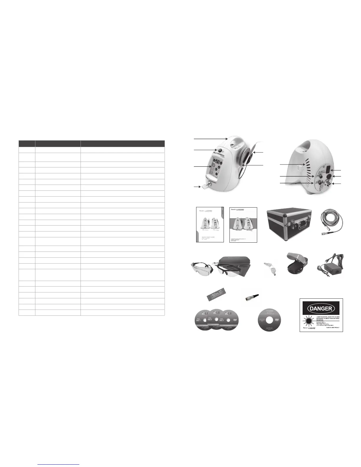
# ITEM DESCRIPTION
1 Key Switch Turns Display of the Unit ON & OFF
2 Control Panel
Displays & Controls the Parameters (e.g. Power Output, Presets, Aiming Beam
& Intensity, & Speaker Volume)
3 Emergency Stop Button Disables the Unit In the Event of an Emergency
4 Handle For Transporting the Unit
5 Handpiece & Holder, Disposable Tip Multi-Tip Handpiece/Fiber with Fiber Spool, Holder, & Disposable Tip
6 Fiber Spool Stores Fiber
7 Wired Foot Control Connector Port Connects Wired Foot Control to the Unit
8 Remote Interlock Connector Connects Interlock to the Unit
9 Cooling Vents Cooling Vents
10 Laser Standby/Ready Button Master ON/OFF Switch
11 AC Power Connector Connects Power Supply to the Unit
12 Fiber Connector Port Connects Fiber to the Unit
13 Quick Start Guide (QSG) Quick Start Guide (QSG)
14 Operating Instructions Manual Operating Instructions Manual
15 Transportation Box Transportation Box (Picasso Only)
16 Wireless Foot Control Cable (Optional)
Optional Cable To Connect Wireless Foot Control Directly To the Device (Battery
Must Be Removed)
17A & 17B Laser Eyewear Protective Goggles (3) ANSI Z87, 800–820 nm, Optical Density (OD) 5+ Protective Eyewear Goggles
18 Laser Eyewear Protective Goggles Case Protective Case
19 Unit Keys Used to Turn Machine Off/On
20 Wireless Foot Control Wireless Foot Control Standard Picasso & Picasso Lite
21 AC Adapter
Connects the Unit & Net Power Supply
Input: 100–240 V 50/60 Hz, Output: 9 V–3A
AC/DC adapter is specified as a part of ME EQUIPMENT.
22 Power Cord Power Cord
23 Articulating Paper Sample of Paper to Be Used for Laser Tip Initiation
24 Remote Interlock Remote Interlock
25 Training Certification DVDs iCLE Training/Certification DVDs
26 Set-Up DVD Set-Up DVD
27 Laser Danger Sign Danger Sign for Operatory (Included at End of Manual)
CONTENTS OF PICASSO & PICASSO LITE