14
(6) Hard disk activity LED: HD LED
This header connects to the hard disk activity indicator light on the case.
(7) Reset switch: RESET
This 2-pin header connects to the case-mounted reset switch for rebooting your
computer without having to turn off your power switch. This is a preferred
method of rebooting in order to prolong the lift of the system’s power supply.
See the figure below.
(8) Power switch: PWR BTN
This 2-pin header connects to the case-mounted power switch to power
ON/OFF the system.
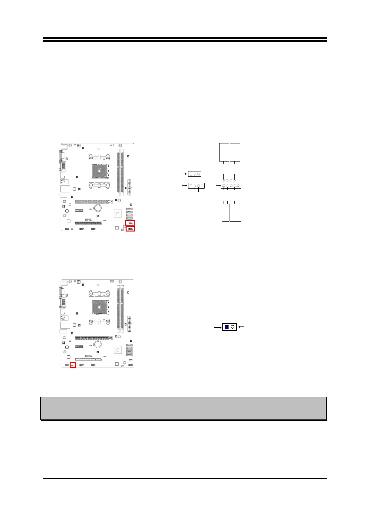
System Case Connections
HDLED
RESET
VC C5
GND
VCC5
PWR LED
PWRBTN
PWRBTN
PWRLED
HDDLE
RSTSW
NC
GND
JW FP1
Pin 1
SPEAK1
SPKR
GND
NC
VCC5
Pin 1
PWRLED1
Pin 1
(9) HDMI-SPDIF Out header: HDMI_SPDIF1
The SPDIF output is capable of providing digital audio to external speakers or
compressed AC3 data to an external Dolby digital decoder. Use this feature only
when your stereo system has digital input function. Some of the VGA Card need
connect SPDIF-IN Connector
,
so its HDMI Port can make sounds .
HDMI_SPDIF Header
1
GND
2
HDMI_SPDIF_OUT
Notice:
the photos used for illustration purpose in this manual are from the model
A75M,
unless otherwise stated.