IMPORTANT — This document contains a wiring diagram, a parts list, and service information. This is customer prop-
erty and is to remain with this unit. Please return to service information pack upon completion of work.
NOTICE: Manufacturer has a policy of continuous product and product data improvement and it
reserves the right to change design and specifications without notice.
THIS INFORMATION IS INTENDED FOR USE BY INDIVIDUALS POS-
SES S ING ADEQUATE BACKGROUNDS OF ELECTRICAL AND ME-
CHANICAL EXPERIENCE. ANY ATTEMPT TO REPAIR A CENTRAL AIR
CONDITION ING PRODUCT MAY RESULT IN PERSONAL INJURY AND
OR PROPERTY DAMAGE. THE MANUFACTURER OR SELLER CAN-
NOT BE RESPON SIBLE FOR THE INTERPRETATION OF THIS INFOR-
MATION, NOR CAN IT ASSUME ANY LIABILITY IN CONNECTION WITH
ITS USE.
RECONNECT ALL GROUNDING DEVICES.
ALL PARTS OF THIS PRODUCT CAPABLE OF CONDUCTING
ELECTRICAL CURRENT ARE GROUNDED. IF GROUNDING
WIRES, SCREWS, STRAPS, CLIPS, NUTS OR WASHERS USED
TO COMPLETE A PATH TO GROUND ARE REMOVED FOR
SERVICE, THEY MUST BE RETURNED TO THEIR ORIGINAL
POSITION AND PROPERLY FASTENED.
WARNING:
HAZARDOUS VOLTAGE - DISCONNECT POWER and DISCHARGE
CAPACITORS BEFORE SERVICING
CAUTION
!
UNIT CONTAINS R-410A REFRIGERANT!
R-410A OPERATING PRESSURE EXCEEDS THE
LIMIT OF R-22. PROPER SERVICE EQUIPMENT IS
REQUIRED. FAILURE TO USE PROPER SERVICE
TOOLS MAY RESULT IN EQUIPMENT DAMAGE OR
PERSONAL INJURY.
SERVICE
USE ONLY R-410A REFRIGERANT AND
APPROVED POE COMPRESSOR OIL.
04/15
PRODUCT SPECIFICATIONS
OUTDOOR UNIT 12
POWER CONNS. — V/PH/HZ 3
MIN. BRCH. CIR. AMPACITY
BR. CIR. PROT. RTG. – MAX. (AMPS)
COMPRESSOR
NO. USED - NO. SPEEDS
VOLTS/PH/HZ
R.L. AMPS 7 - L.R. AMPS
FACTORY INSTALLED
START COMPONENTS 8
INSULATION/SOUND BLANKET
COMPRESSOR HEAT
OUTDOOR FAN
DIA. (IN.) - NO. USED
TYPE DRIVE - NO. SPEEDS
CFM @ 0.0 IN. W.G. 4
NO. MOTORS - HP
MOTOR SPEED R.P.M.
VOLTS/PH/HZ
F.L. AMPS
OUTDOOR COIL — TYPE
ROWS - F.P.I.
FACE AREA (SQ. FT.)
TUBE SIZE (IN.)
REFRIGERANT CONTROL
REFRIGERANT
LBS. — R-410 (O.D. UNIT) 5
FACTORY SUPPLIED
LINE SIZE - IN. O.D. GAS 6
LINE SIZE - IN. O.D. LIQ. 6
CHARGING SPECIFICATION
SUBCOOLING
DIMENSIONS
CRATED (IN.)
WEIGHT
SHIPPING (LBS.)
NET (LBS.)
Service Facts
© 2015 American Standard Heating & Air Conditioning
4A6H4018D-SF-1A-EN
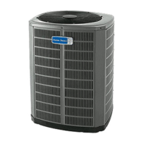
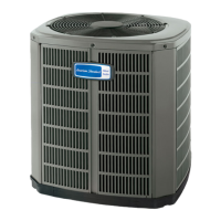
Split System
Heat Pump
4A6H4018D1000A
1 Certified in accordance with the Air-Source Unitary Heat Pump Equipment certification
program, which is based on AHRI standard 210/240.
2 Rated in accordance with AHRI standard 270.
3 Calculated in accordance with Natl. Elec. Codes. Use only HACR circuit breakers or
fuses.
4 Standard Air — Dry Coil — Outdoor
5 This value approximate. For more precise value see unit nameplate.
6 Max. linear length 60 ft.; Max. lift - Suction 60 ft.; Max lift - Liquid 60 ft.
For greater length consult refrigerant piping software Pub. No. 32-3312-0*
(* denotes latest revision).
7 This value shown for compressor RLA on the unit nameplate and on this specification
sheet is used to compute minimum branch circuit ampacity and max. fuse size. The
value shown is the branch circuit selection current.
8 No means no start components. Yes means quick start kit components. PTC means
positive temperature coefficient starter.
CONTAINS REFRIGERANT!
SYSTEM CONTAINS OIL AND REFRIGERANT UNDER
HIGH PRESSURE. RECOVER REFRIGERANT TO RELIEVE
PRESSURE BEFORE OPENING SYSTEM.
Failure to follow proper procedures can result in personal
illness or injury or severe equipment damage.
CAUTION
!
HOT SURFACE!
DO NOT TOUCH TOP OF COMPRESSOR.
May cause minor to severe burning.
CAUTION
!
4A6H4018D1000A
208/230/1/60
9
15
DURATION™
1 - 1
208/230/1/60
6.4 - 38.6
YES
NO
NO
PROPELLER
23 - 1
DIRECT - 1
3150
1 - 1/8
825
200/230/1/60
0.77
SPINE FIN™
1 - 24
13.43
3/8
EXPANSION VALVE
5 LBS. - 14 OZ.
YES
5/8
3/8
12°F
H X W X D
34 x 30.1 x 33
204
176
TUBING INFORMATION
LINE TYPE
REFRIGERANT TO ADD AT SPECIFIED
ADDITIONAL LENGTH
Suction Liquid 20 ft 30 ft 40 ft 50 ft 60 ft
5/8" 3/8" 3 oz 8 oz 14 oz 20 oz 25 oz




 Loading...