Do you have a question about the American Standard 4A6H5036H and is the answer not in the manual?
Covers critical safety warnings and precautions for installation and operation.
Specifies maximum total length and vertical change for refrigerant lines.
Table detailing refrigerant line and service valve connection sizes for various models.
Step-by-step instructions for preparing and brazing refrigerant lines.
Method for charging the system based on subcooling for higher outdoor temperatures.
Procedure for calculating refrigerant charge using the weigh-in method for low outdoor temperatures.
A fault chart to help diagnose and resolve system issues based on observed symptoms.
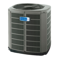
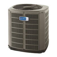
This document serves as an installer's guide for American Standard Heat Pumps, specifically the 4A6H5 model. It outlines the necessary steps and precautions for the proper installation, start-up, and maintenance of the unit, emphasizing compliance with national, state, and local codes. The guide is intended for individuals with adequate electrical and mechanical experience, as improper installation or servicing can lead to personal injury or property damage.
The primary function of this device is to provide heating and air conditioning for residential or commercial buildings. As a heat pump, it is designed to efficiently transfer heat, offering both cooling in warmer months and heating in colder periods. The unit operates with R-410A refrigerant, which requires specific handling procedures and approved service equipment due to its higher operating pressures compared to R-22.
Key usage features include its adaptability to various installation environments. The guide provides detailed considerations for unit placement, including minimum clearances from walls, shrubbery, and other structures to ensure adequate airflow and prevent noise or vibration transmission to the building. For installations on roofs, it highlights the importance of ensuring the roof can support the unit's weight and recommends isolation to mitigate sound and vibration. In cold climates, specific precautions are advised, such as elevating the unit to allow for snow and ice drainage during defrost cycles and installing snow drift barriers to prevent accumulation.
The installation process is meticulously detailed, starting with preparing the unit by checking for damage and removing it from its pallet. Setting the unit involves placing it on a support pad that is level, separate from any structure, and large enough to allow for drainage, all while complying with local codes.
Refrigerant line considerations are a critical aspect of the installation. The guide specifies the correct line sizes and service valve connection diameters for different models. It notes that the outdoor condensing units are factory charged for a specific length of connecting line and the smallest indoor evaporative coil match. Any deviation from these conditions, such as longer line lengths or larger indoor coils, necessitates a final refrigerant charge adjustment. The importance of insulating the vapor line and preventing direct metal-to-metal contact between the liquid and vapor lines is also stressed. For retrofit applications, the guide advises ensuring existing refrigerant lines and indoor coils are the correct size and free of leaks, acid, and oil, with all joints brazed, not soldered.
Refrigerant line routing includes precautions to prevent noise and vibration transmission, recommending isolation-type hangers when fastening lines to structural elements and insulating lines passing through walls or sills. Minimizing 90-degree turns in the lines is also suggested for optimal performance.
Brazing the refrigerant lines involves several steps: deburring and cleaning pipe ends, removing pressure tap caps and valve cores, purging lines with dry nitrogen, and wrapping wet rags around valve bodies to prevent heat damage during brazing. For units with field-installed external driers, ensuring correct directional flow is crucial.
Maintenance features are integrated throughout the installation process to ensure long-term reliability. After brazing, a refrigerant line leak check is performed by pressurizing the lines and evaporator coil with dry nitrogen and checking for leaks with a soapy solution. Any leaks must be repaired before proceeding.
Evacuation of the refrigerant lines and indoor coil is a critical step, requiring evacuation until a micron gauge reads no higher than 350 microns, followed by observing the gauge for stability. This ensures the removal of non-condensable gases and moisture from the system.
Opening the service valves is done carefully, with specific instructions for both gas and liquid service valves to prevent abrupt release of system charge and potential injury.
Electrical connections are detailed for both low and high voltage. Low voltage wiring length limits are provided based on wire size to ensure proper operation. High voltage wiring must comply with national, state, and local codes, and a separate disconnect switch is required at the outdoor unit. Flexible electrical conduit is recommended for high voltage connections to minimize noise transmission. Proper grounding of the outdoor unit is also emphasized.
The start-up procedure includes ensuring all previous installation steps are completed, setting the thermostat to OFF, applying power to the units, and waiting one hour before starting if a compressor crankcase heater accessory is used and the outdoor ambient is below 70°F.
System charge adjustment is a key maintenance feature, with detailed instructions for subcooling charging in cooling mode for outdoor temperatures above 55°F. This involves measuring liquid line temperature and pressure, and using a charging chart to determine the proper liquid gauge pressure. The guide provides steps for adding or recovering refrigerant to achieve the correct charge. For outdoor temperatures below 55°F, the weigh-in method in heating mode is recommended.
Finally, checkout procedures and troubleshooting steps are provided to ensure proper performance and safe operation. This includes a comprehensive checklist covering refrigerant lines, insulation, electrical connections, airflow, and drain lines. A system faults table assists in diagnosing common issues, categorizing them by refrigerant circuit, electrical problems, and defrost malfunctions, and indicating primary and secondary causes.
Overall, the guide ensures that the American Standard Heat Pump is installed and maintained to deliver maximum efficiency, optimum performance, and the best overall system reliability, adhering to industry standards and safety protocols.
| Brand | American Standard |
|---|---|
| Model Number | 4A6H5036H |
| Category | Heat Pump |
| SEER Rating | 16 |
| HSPF Rating | 9.0 |
| Refrigerant | R-410A |
| Voltage | 208/230V |
| Phase | 1 |
| Cooling Capacity (BTU/h) | 30000 |
| Heating Capacity (BTU/h) | 30000 |
| Sound Level (dBA) | 72 |
| Cooling Capacity | 2.5 Tons |
| Heating Capacity | 2.5 Ton |
| Compressor Type | Single-Stage |