© 2005 American Standard Inc. All Rights Reserved
Since the manufacturer has a policy of continuous product
and product data improvement, it reserves the right to
change design and specifications without notice.
11-BC11D1-2
IMPORTANT — This Document is customer property and is to remain with this unit. Please return to service information pack
upon completion of work.
These instructions do not cover all variations in systems
nor provide for every possible contingency to be met in
connection with installation. All phases of this installa-
tion must comply with NATIONAL, STATE AND LOCAL
CODES. Should further information be desired or should par-
ticular problems arise which are not covered sufficiently for the
purchaser’s purposes, the matter should be referred to your
installing dealer or local distributor.
A. GENERAL
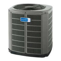
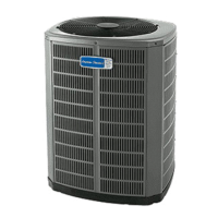
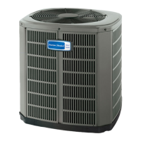
The following instructions cover 4A6H6 Heat Pump Units.
NOTICE: These outdoor units may be used with indoor
units equipped with Thermostatic Expansion Valve only.
▲ WARNIN
:
These units use R-410A refrig-
erant which operates at 50 to 70% higher pressures than
R-22. Use only R-410A approved service equipment. Refrig-
erant cylinders are painted a “Rose” color to indicate the
type of refrigerant and may contain a “dip” tube to allow for
charging of liquid refrigerant into the system. All R-410A
systems use a POE oil that readily absorbs moisture from
the atmosphere. To limit this “hygroscopic” action, the
system should remain sealed whenever possible. Never
break a vacuum with air and
always change the driers
when opening the system for component replacement.
Check for transportation damage after unit is uncrated. Report
promptly, to the carrier, any damage found to the unit.
To determine the electrical power requirements of the unit, refer
to the nameplate of the unit. The electrical power available must
agree with that listed on the nameplate.
The Heat Pump has been designed and manufactured to with-
stand and operate in severe winter conditions. However, there
are precautionary steps which should be taken at the time of
installation which will help assure the efficient operation of the
unit. It is recommended that these precautions be taken
for units being installed in areas where snow accumula-
tion and prolonged below freezing temperatures occur.
1. Units should be elevated 3 to 12 inches above the pad or
rooftop, depending on local weather. This additional height will
allow better drainage of snow and ice (melted during defrost cycle)
prior to its refreezing. This should prevent a buildup of ice around
the unit which occurs when unit is not elevated. Insure that
drain holes in unit base pan are not obstructed prevent-
ing draining of defrost water.
2. If possible, avoid locations that are likely to accumulate snow
drifts. If not possible, a snow drift barrier should be installed
around the unit to prevent a buildup of snow on the sides of the
unit and should be of sufficient distance from the unit to prevent
restriction of airflow to and from the unit. Also allow for proper
maintenance space. The barrier should be constructed of mate-
rials which will blend in with the building design.
Heat Pumps
CAUTION
!
UNIT CONTAINS R-410A REFRIGERANT!
R-410A OPERATING PRESSURE EXCEEDS THE
LIMIT OF R-22. PROPER SERVICE EQUIPMENT IS
REQUIRED. FAILURE TO USE PROPER SERVICE
TOOLS MAY RESULT IN EQUIPMENT DAMAGE OR
PERSONAL INJURY.
SERVICE
USE ONLY R-410A REFRIGERANT AND
APPROVED POE COMPRESSOR OIL.
INSTALLER'S GUIDE
ALL phases of this installation must comply with NATIONAL, STATE AND LOCAL CODES
5 FT. ABOVE UNIT-UNRESTRICTED
1
Models:
4A6H6024,036,048 & 060B