EasyManua.ls Logo

American Standard 4A6H7 Series - User Manual

American Standard 4A6H7 Series
24 pages
Print Icon
To Next Page IconTo Next Page
Loading...
11-BC35D1-4-EN
ALL phases of this installation must comply with NATIONAL, STATE AND LOCAL CODES
IMPORTANT — This Document is customer property and is to remain with this unit. Please return to service informa-
tion pack upon completion of work.
These instructions do not cover all variations in systems or provide for every possible contingency to be met in connection with
the installation. Should further information be desired or should particular problems arise which are not covered sufficiently for the
purchaser’s purposes, the matter should be referred to your installing dealer or local distributor.
Note: The manufacturer recommends installing only approved matched indoor and outdoor systems. All of the manufacture’s split
systems are AHRI rated only with TXV/EEV indoor systems. Some of the benefits of installing approved matched indoor and out-
door split systems are maximum efficiency, optimum performance and the best overall system reliability.
4A6H7
Installer’s Guide
Heat Pumps
Table of Contents
Section 1. Safety ..................................................................................... 2
Section 2. Unit Location Considerations.............................................. 3
Section 3. Unit Preparation .................................................................... 5
Section 4. Setting the Unit ..................................................................... 5
Section 5. Refrigerant Line Considerations ......................................... 6
Section 6. Refrigerant Line Routing ..................................................... 8
Section 7. Refrigerant Line Brazing ...................................................... 8
Section 8. Refrigerant Line Leak Check ............................................. 10
Section 9. Evacuation ........................................................................... 12
Section 10. Service Valves ................................................................... 12
Section 11. Electrical - Low Voltage .................................................... 13
Section 12. Electrical - High Voltage ................................................... 15
Section 13. Start Up .............................................................................. 16
Section 14. System Charge Adjustment ............................................. 17
Section 15. Checkout Procedures and Troubleshooting ................... 23
Question and Answer IconNeed help?

Do you have a question about the American Standard 4A6H7 Series and is the answer not in the manual?

Overview

This document is an installer's guide for American Standard Heat Pumps, specifically the 4A6H7 model, and is identified by the document number 11-BC35D1-4-EN. It provides comprehensive instructions for the installation, startup, and maintenance of these units, emphasizing compliance with national, state, and local codes. The guide is intended for individuals with adequate electrical and mechanical experience, warning against personal injury or property damage if proper procedures are not followed.

Function Description:

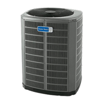
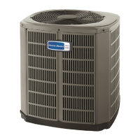
The American Standard 4A6H7 heat pump is designed for heating and air conditioning applications. It uses R-410A refrigerant, which operates at higher pressures than R-22, and requires R-410A approved service equipment. The system is designed for optimal performance, efficiency, and reliability when installed as a matched indoor and outdoor system, as rated by AHRI (Air-Conditioning, Heating, and Refrigeration Institute) with TXV/EEV indoor systems. The unit's primary function is to transfer heat, providing cooling in warmer conditions and heating in colder conditions.

Important Technical Specifications:

  • Refrigerant: R-410A. This refrigerant requires specific handling due to its higher operating pressures and the use of POE (Polyolester) oil, which is hygroscopic (readily absorbs moisture). Systems exposed to the atmosphere for more than 4 hours require compressor oil replacement and drier changes.
  • Unit Dimensions and Weight (Estimated):
    • 4A6H7024A: 41" H x 34" D x 37" W, 236 lbs
    • 4A6H7036B: 41" H x 34" D x 37" W, 210 lbs
    • 4A6H7048A: 45" H x 34" D x 37" W, 292 lbs
    • 4A6H7060A: 45" H x 34" D x 37" W, 293 lbs
  • Refrigerant Piping Limits:
    • Maximum TOTAL line length (outdoor to indoor unit): 150 feet (including lift).
    • Maximum vertical change: 50 feet.
    • Specific line sizes and service valve connection sizes are provided in Table 5.1, with alternate line sizes also listed. For example, a 4A6H7024A unit typically uses a 5/8" vapor line and 3/8" liquid line, with corresponding service valve connections.
  • Factory Charge: Units are factory charged with the system charge required for the outdoor condensing unit, 15 feet of tested connecting line, and the smallest indoor evaporative coil match. Adjustments are necessary for longer line lengths or larger indoor evaporative coils.
  • Low Voltage Wiring:
    • 18 AWG: 150 Ft. Max. Wire Length
    • 16 AWG: 225 Ft. Max. Wire Length
    • 14 AWG: 300 Ft. Max. Wire Length
  • Defrost Termination Temperatures:
    • As Shipped (>22°F outdoor temp): 47°F termination.
    • As Shipped (10°F-22°F outdoor temp): ODT + 25°F termination.
    • As Shipped (6°F-10°F outdoor temp): 35°F termination.
    • Cut Jumper 2 (>30°F outdoor temp): 47°F termination.
    • Cut Jumper 2 (6°F-30°F outdoor temp): 70°F termination.
    • All (<6°F outdoor temp): 12 min. or 35°F every 3 hrs. termination.

Usage Features:

  • Installation Flexibility: The unit can be installed on a support pad (concrete slab) or rooftop, with specific recommendations for pad size, levelness, drainage, and structural isolation to prevent vibration.
  • Location Considerations: Recommendations are provided to ensure optimal performance and minimize nuisance, such as maintaining 5 feet of unrestricted space above the unit, 3 feet of clearance for service access, and at least 12 inches from walls or shrubbery for adequate airflow. Locations near bedrooms or windows where defrost vapor could be annoying should be avoided.
  • Cold Climate Adaptations: For areas with snow accumulation or prolonged freezing temperatures, units should be elevated 3-12 inches above the pad/rooftop to allow for drainage of melted snow/ice. Snow drift barriers are recommended to prevent snow buildup on the unit's sides.
  • Refrigerant Line Routing: Precautions are detailed to prevent noise from vibration transmission, including using isolation hangers when fastening lines to structural elements and insulating lines running through walls or sills. Minimizing 90° turns is also advised.
  • Charging Methods:
    • Subcooling Charging (Above 55°F Outdoor Temp.): This is the recommended method for charging in cooling mode. It involves measuring liquid line temperature and pressure, then comparing to a charging chart based on total line length and lift.
    • Weigh-In Method (Below 55°F Outdoor Temp. or Initial Installation): This method is recommended for heating mode charging at lower outdoor temperatures or when power is unavailable. It involves calculating additional refrigerant needed based on line length beyond the factory 15 feet.
  • Defrost Control: The unit features a selectable defrost termination temperature, with a default of 47°F. Jumper J2 can be cut to achieve a 70°F termination when ambient temperatures are at or below 30°F. Test pins are available on the defrost board for diagnostic purposes (TEST_COMMON, TST, FRC_DFT).

Maintenance Features:

  • Leak Check: After brazing refrigerant lines, the system must be pressurized to 150 PSIG with dry nitrogen and checked for leaks using a soapy solution.
  • Evacuation: The refrigerant lines and indoor coil must be evacuated to a micron gauge reading of no higher than 350 microns. Evacuation is complete if the gauge does not rise above 500 microns in one minute after closing the valve to the vacuum pump.
  • Service Valve Operation: Instructions are provided for safely opening the gas and liquid service valves, emphasizing caution with the liquid line valve to prevent abrupt release of system charge.
  • System Stabilization: After any charge adjustments, the system must be operated for a minimum of 20 minutes to stabilize before accurate measurements can be made.
  • Checkout Procedures: A comprehensive checklist is provided for final inspection, including verifying refrigerant lines, insulation, drain line function, airflow, electrical connections, and overall system operation in all modes.
  • Troubleshooting Guide: A detailed "SYSTEM FAULTS" table helps diagnose issues based on symptoms (e.g., head pressure too high/low, compressor won't start, unit icing up) and identifies primary and secondary causes, categorized by refrigerant circuit, electrical, and defrost problems.
  • Coastal Considerations: For installations within one mile of salt water, the addition of BAYSEAC001 (Seacoast Kit) is required for models without factory-supplied Seacoast Salt Shields.

The guide stresses the importance of proper installation and maintenance to ensure the longevity and efficient operation of the heat pump. It also highlights the manufacturer's policy of continuous product improvement and the right to change designs and specifications without notice.

American Standard 4A6H7 Series Specifications

General IconGeneral
BrandAmerican Standard
Model4A6H7 Series
CategoryHeat Pump
LanguageEnglish

Related product manuals