EasyManua.ls Logo

American Standard 4A7A3018-060A1000A - User Manual

American Standard 4A7A3018-060A1000A
8 pages
Print Icon
To Next Page IconTo Next Page
Loading...
© 2006 American Standard Inc. All Rights Reserved
Since the manufacturer has a policy of continuous product
and product data improvement, it reserves the right to
change design and specifications without notice.
11-AC22D1-1
These instructions do not cover all variations in systems
nor provide for every possible contingency to be met in
connection with installation. All phases of this installa-
tion must comply with NATIONAL, STATE AND LOCAL
CODES. Should further information be desired or should
particular problems arise which are not covered sufficiently for
the purchaser’s purposes, the matter should be referred to your
installing dealer or local distributor.
A. GENERAL
WARNIN
G
:
This information is intended
for use by individuals possessing adequate backgrounds
of electrical and mechanical experience. Any attempt to
repair a central air conditioning product may result in
personal injury and or property damage. The manufac-
turer or seller cannot be responsible for the interpreta-
tion of this information, nor can it assume any liability in
connection with its use.
NOTE: AMERICAN STANDARD HAS ALWAYS RECOM-
MENDED INSTALLING AMERICAN STANDARD AP-
PROVED MATCHED INDOOR AND OUTDOOR SYSTEMS.
THE BENEFITS OF INSTALLING APPROVED MATCHED
SYSTEMS ARE MAXIMUM EFFICIENCY, OPTIMUM PER-
FORMANCE AND BEST OVERALL SYSTEM RELIABILITY.
WARNIN
G
:
These units use R-410A refrig-
erant which operates at 50 to 70% higher pressures than
R-22. Use only R-410A approved service equipment. Re-
frigerant cylinders are painted a “Rose” color to indicate
the type of refrigerant and may contain a “dip” tube to
allow for charging of liquid refrigerant into the system.
All R-410A systems use a POE oil that readily absorbs
moisture from the atmosphere. To limit this “hygroscopic”
action, the system should remain sealed whenever pos-
sible. If a system has been open to the atmosphere for
more than 4 hours, the compressor oil must be replaced.
Never break a vacuum with air and
always change the
driers when opening the system for component replace-
ment. For specific handling concerns with R-410A and
POE oil, reference Retrofit Bulletin APB2001-01.
Check for transportation damage after unit is uncrated. Report
promptly, to the carrier, any damage found to the unit.
To determine the electrical power requirements of the unit, refer
to the nameplate of the unit. The electrical power available must
agree with that listed on the nameplate.
B. LOCATION AND PREPARATION OF THE UNIT
1. When removing unit from the pallet, notice the tabs on the
basepan. Remove tabs by cutting with a sharp tool as shown on
page 2, Figure 2, and slide unit off of pallet.
2. The unit should be set on a level support pad at least as large
as the unit base pan, such as a concrete slab.
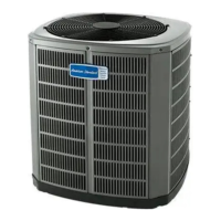
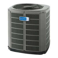
Condensing Units
INSTALLER'S GUIDE
ALL phases of this installation must comply with NATIONAL, STATE AND LOCAL CODES
5 FT. ABOVE UNIT — UNRESTRICTED
1
Models:
4A7A3018-060A1000A
IMPORTANT — This Document is customer property and is to remain with this unit. Please return to service information pack
upon completion of work.
CAUTION
!
UNIT CONTAINS R-410A REFRIGERANT!
R-410A OPERATING PRESSURE EXCEEDS THE
LIMIT OF R-22. PROPER SERVICE EQUIPMENT IS
REQUIRED. FAILURE TO USE PROPER SERVICE
TOOLS MAY RESULT IN EQUIPMENT DAMAGE OR
PERSONAL INJURY.
SERVICE
USE ONLY R-410A REFRIGERANT AND
APPROVED POE COMPRESSOR OIL.
Question and Answer IconNeed help?

Do you have a question about the American Standard 4A7A3018-060A1000A and is the answer not in the manual?

Overview

This document outlines the installation and maintenance procedures for a condensing unit, specifically models 4A7A3018-060A1000A. It serves as an installer's guide, providing comprehensive instructions for safe and efficient setup, operation, and troubleshooting.

Function Description

The condensing unit is a critical component of a heating, ventilation, and air conditioning (HVAC) system, designed to dissipate heat from the refrigerant. It works in conjunction with an indoor air handler or furnace to provide cooling. The unit utilizes R-410A refrigerant, a common and environmentally preferred choice for modern HVAC systems. The guide emphasizes the importance of proper installation to ensure optimal performance, energy efficiency, and longevity of the system.

Important Technical Specifications

  • Refrigerant Type: R-410A. The guide strongly cautions against using R-22 or other refrigerants due to potential damage and safety hazards.
  • Electrical Requirements: The unit requires a dedicated power supply that complies with local codes. Low voltage wiring should be No. 18 AWG minimum conductor.
  • Refrigerant Line Lengths: Maximum recommended length for refrigerant lines from outdoor to indoor unit is 60 feet. Maximum lift for the suction line (if outdoor unit is above air handler) or liquid line (if air handler is above condensing unit) is also 60 feet.
  • Clearances: A minimum of 12 inches clearance from any wall or surrounding shrubbery is required for adequate airflow. The top discharge area must be unrestricted for at least five feet above the unit.
  • Factory Charge: Units are factory charged with the system charge required when using 15 feet of rated connecting line. The unit nameplate charge is based on 25 feet of line set. Final refrigerant charge adjustment is necessary based on the actual line length.
  • Wiring Diagrams: Detailed typical field wiring diagrams are provided for various configurations, including 1-stage or 2-stage furnaces, and variable speed air handlers, with and without outdoor thermostats (ODT).
  • Subcooling Charging: A table is provided for subcooling charging corrections based on total refrigerant line length, ensuring accurate refrigerant levels for optimal performance.
  • Dimensions: Outline drawings with dimensions in millimeters (inches) are provided for different base sizes (Base 3 and Base 4), including mounting hole locations.

Usage Features

  • R-410A Refrigerant: The units are specifically designed for R-410A refrigerant. Installers are warned against using R-22, as it can cause damage to the compressor and void the warranty.
  • Scroll Compressor Applications: A caution is issued regarding hot dome temperatures in scroll compressor applications, advising against touching the top of the compressor to prevent burns.
  • Service Valves: The brass liquid and gas line service valves are factory shipped in the seated position to hold the factory charge. Instructions are provided for opening these valves, emphasizing caution to turn the valve stem counterclockwise only until it contacts the rolled edge, without applying torque.
  • Basepan Tab Removal: Instructions are given for removing basepan tabs, which is likely part of the installation process to secure the unit or prepare it for drainage.
  • Refrigerant Line Installation: Detailed steps are provided for running refrigerant lines, including determining the most practical way, considering bends, routing, uncoiling, and securing the tubing. Brazing is required for all joints, not soldering.
  • Noise Prevention: Precautions are outlined to prevent noise transmission from refrigerant lines to the building structure, such as using isolation type hangers when fastening to floor joists or framing, and insulating/isolating lines where they pass through walls or sills.
  • Outdoor Unit Placement: Guidelines for outdoor unit placement include ensuring adequate airflow, providing clearance for service access, and avoiding locations where excess roof run-off water could pour directly onto the unit. It is also recommended not to locate units close to bedrooms to minimize noise disturbance.
  • Roof Mounting: If the outdoor unit is mounted on a roof, the roof must be able to support the unit's weight, and proper isolation is recommended to prevent vibration transmission to the building structure.

Maintenance Features

  • Final Refrigerant Charge Adjustment: After installation, a final refrigerant charge adjustment is necessary using the charging information provided in the guide or the unit Service Facts.
  • Leak Check: A crucial step in the checkout procedure is to perform a thorough leak check using a nitrogen purge and brazing alloy without flux. This involves pressurizing the system with nitrogen and checking all brazed connections with soap bubbles.
  • Evacuation: After leak checking, the system must be evacuated to a deep vacuum (500 microns or less) to remove all non-condensable gases and moisture. Instructions for connecting manifold gauges and a vacuum pump are provided.
  • Compressor Start-Up: Instructions for compressor start-up include ensuring the thermostat is in the OFF position, applying power, and allowing the compressor crankcase heater to operate for one hour before starting the compressor to prevent potential compressor overload.
  • Troubleshooting Chart: A comprehensive troubleshooting chart is included, listing various system faults (refrigerant circuit, electrical, and mechanical) and their potential primary and secondary causes, aiding in diagnosing and resolving issues.
  • Checkout Procedure: A checklist of items to verify after installation is provided, including refrigerant line leak check, suction lines and fittings, refrigerant lines secured and isolated, passages through masonry, electrical connections, and overall system operation.
  • Service Valve Operation: The guide details how to operate the service valves for both liquid and gas lines, which are used during charging and servicing. The pressure tap service port opens only to the field brazing side of the valve when the valve is in the seated position.

American Standard 4A7A3018-060A1000A Specifications

General IconGeneral
BrandAmerican Standard
Model4A7A3018-060A1000A
CategoryHeat Pump
LanguageEnglish

Related product manuals