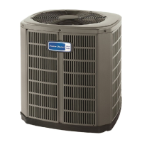
Do you have a question about the American Standard 4A7A7048B and is the answer not in the manual?
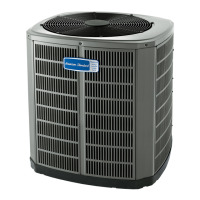
| Model Number | 4A7A7048B |
|---|---|
| Brand | American Standard |
| Category | Air Conditioner |
| Type | Split System |
| SEER Rating | 16 |
| Refrigerant Type | R-410A |
| Voltage | 208/230V |
| Phase | 1 |
| Sound Level (Outdoor Unit) | 74 dB |
| Stages | Single Stage |
| Cooling Capacity | 4 Ton |
| HSPF | Not Applicable |
| Cooling Capacity (BTU) | 48000 BTU |
| Compressor Type | Single Stage Scroll |
Details the physical dimensions and estimated weight of the 4A7A7048B model.
Specifies maximum total and vertical lengths for refrigerant lines, and line sizes.
Provides guidance on optimal placement to ensure proper airflow, avoid noise, and prevent water/icicle damage.
Offers precautions for units in areas with snow and prolonged freezing temperatures, including elevation and snow barriers.
Outlines steps for checking the unit for damage and removing it from the pallet.
Details requirements for support pads, including size, levelness, separation from structure, and drainage.
Provides a table detailing line sizes and service valve connection sizes for different models.
Explains the factory charge is for specific line lengths and smallest coil; adjustments may be needed.
Instructions to determine and record the total line length and vertical change for later calculations.
Emphasizes the importance of insulating the vapor line and preventing metal-to-metal contact.
Details precautions for routing lines to prevent vibration transmission and comply with codes, including isolation and minimizing turns.
Provides step-by-step instructions for preparing and brazing refrigerant lines, including deburring and cleaning.
Details the procedure for pressurizing the system with dry nitrogen and checking for leaks using soapy solution.
Describes the process of evacuating the system to a specific micron level using a vacuum pump and micron gauge.
Provides steps for opening the gas service valve, including removing the cap and turning the stem.
Explains how to safely open the liquid line service valve, emphasizing caution due to pressure.
Details the maximum allowable lengths for low voltage wiring based on wire gauge (AWG).
Illustrates wiring connections for different thermostat and air handler configurations (TEM 6, TAM 7, Variable Speed).
Addresses high voltage power supply requirements, agreeing with the nameplate and complying with codes.
Recommends installing a separate disconnect switch at the outdoor unit for safety and convenience.
Specifies grounding the outdoor unit according to national, state, and local code requirements.
Details the step-by-step procedure for starting the system, including thermostat settings and power application.
Explains how to measure outdoor and indoor temperatures, noting subcooling is for above 55°F outdoor temps.
Details the subcooling method for charging systems in cooling mode when outdoor temperatures are above 55°F.
Recommends weighing-in charge for outdoor temps below 55°F, detailing the weigh-in method and charge multiplier.
Lists final operational and checkout procedures to ensure proper performance and safe operation of the system.
Provides a system faults chart cross-referencing common issues with potential causes and checks for refrigerant and electrical circuits.





 Loading...