EasyManua.ls Logo

American Standard 4A7V0060A1000B User Manual

American Standard 4A7V0060A1000B
72 pages
To Next Page IconTo Next Page
Page #1 background imageLoading...
Page #1 background image
SSAAFFEETTYY WWAARRNNIINNGG
Only qualified personnel should install and service the equipment. The installation, starting up, and servicing of heating, ventilating, and
air-conditioning equipment can be hazardous and requires specific knowledge and training. Improperly installed, adjusted or altered
equipment by an unqualified person could result in death or serious injury. When working on the equipment, observe all precautions in the
literature and on the tags, stickers, and labels that are attached to the equipment.
August 2017
44AA--VV00--SSFF--11GG--EENN
Variable Speed AccuLink
Heat Pumps and Air Conditioners
4A6V0024A1000B
4A6V0036A1000B
4A6V0048A1000B
4A6V0060A1000B
4A7V0024A1000B
4A7V0036B1000B
4A7V0048A1000B
4A7V0060A1000B
4A7V0061A1000B
Scan to see help
videos on this
product
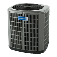
NNoottee:: “Graphics in this document are for representation only.
Actual model may differ in appearance.”
Service Facts

Table of Contents

Question and Answer IconNeed help?

Do you have a question about the American Standard 4A7V0060A1000B and is the answer not in the manual?

American Standard 4A7V0060A1000B Specifications

General IconGeneral
BrandAmerican Standard
Model4A7V0060A1000B
CategoryAir Conditioner
LanguageEnglish

Summary

SAFETY SECTION — OUTDOOR

Outdoor Safety Warnings and Precautions

Details critical safety information for outdoor unit service, including electrical hazards and refrigerant handling.

Subcooling Charging Method

Subcooling Charging Procedure Details

Explains the recommended subcooling method for charging systems in cooling mode.

Weigh-In Method for Refrigerant Charging

Calculating Refrigerant Charge: New Installations

Worksheet and steps for calculating refrigerant charge for new system installations.

Calculating Refrigerant Charge: Sealed-System Repairs

Steps for calculating refrigerant charge during sealed-system repairs.

Integrated Variable Speed Control (IVSC) Connections

IVSC Input/Output Terminal Assignments

Diagram showing the integrated variable speed control board's inputs and outputs.

Sequence of Operation

Control Operational Overview

Description of how the IVSC manages system operation based on comfort control signals.

Cooling Mode Operation

Operation of the system in cooling mode, including startup and capacity modulation.

Heat Pump Cooling Mode of Operation

Specific cooling operation for heat pump systems, including SOV pulsing.

Sequence of Operation (Continued)

Defrost Control (Heat Pump only)

Demand Defrost Operation and Initiation

Explanation of how demand defrost is determined and enabled based on sensor inputs.

Variable Speed Alert Codes

Communication Loss Troubleshooting

Troubleshooting Steps for Communication Loss

Flowchart to diagnose and resolve communication loss issues with the system.

Breaker Trip Procedure

Flowchart for Breaker Trip Diagnosis

Step-by-step guide to troubleshoot and identify the cause of breaker trips.

Start Compressor Troubleshooting

Flowchart for Diagnosing Compressor Startup Issues

Procedure to follow when encountering issues during compressor startup.

Run Drive Diagnostic Test

Procedure for Running Drive Diagnostics

Guide to performing drive diagnostic tests and interpreting results.

Inverter Temperature Troubleshooting

Diagnosing Inverter and Rectifier Temperature Issues

Flowchart to address issues related to inverter and rectifier temperature warnings.

Electronic Expansion Valve (EEV) Troubleshooting

EEV Troubleshooting Flowchart

Guide for troubleshooting EEV operation in heating and cooling modes.

Related product manuals