ALL phases of this installation must comply with NATIONAL, STATE AND LOCAL CODES
ACONT402AN32DA
3 Heat (Gas, Oil* or Elec) / 2 Cool / Heat Pump, Dual
Fuel
(Factory set for 2H/2C gas/cooling applications, BK Output enabled)
Electronic Non-Programmable
3 - 16 Wire Hookup (2 for Outdoor Sensor)
(2 for Optional Remote Indoor Sensor, 2 for Optional Humidistat)
Installer’s Guide
Premium
Introduction
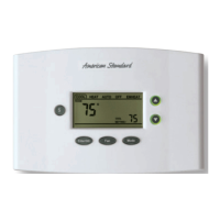
ACONT402AN32DA is a digital non-programmable 3Heat/ 2
Cool/Heat Pump/ Heat-Cool wall mounted low voltage
(24VAC) Comfort Control with backlit LCD and keypad. It
maintains room temperature by controlling the operation of
heating, cooling, heat pump and dual fuel systems. The
Comfort Control is easily configured for heat pump or cooling
only and gas or electric or dual fuel heat applications via the
user friendly Installer Setup menu. The Comfort Control
features include separate heating and cooling setpoints,
selectable auto or manual changeover, adjustable energy
saving mode, adjustable filter reminder, outdoor temperature
sensing, remote room sensing and remote humidistat input.
Setup selections and diagnostics are stored indefinitely in the
Comfort Controls nonvolatile memory eliminating the need
for battery backup.
Safety Considerations
Read the following manufacturer instructions carefully.
Follow all local codes during installation. All wiring must
conform to local and national electrical codes. Improper wiring
or installation may damage the comfort control.
Recognize safety information. This is the safety alert symbol
!
. When you see this symbol on the equipment and in the
instruction manual, be alert to the potential for personal
injury.
Understand the signal words DANGER, WARNING and
CAUTION. These words are used with the safety-alert
symbol. DANGER identifies the most serious hazards which
will result in severe personal injury or death. WARNING
signifies a hazard which could result in personal injury or
death. CAUTION is used to identify unsafe practices which
could result in minor personal injury or product and property
damage.
Note: Read the entire instruction manual before starting the
installation.
Application Hook Up Diagrams
Dual Fuel* FIG
1-2 Stage/Step Heat Pump 2 Stage VS Gas Furnace w/ BK DF-1
2 Stage Heat Pump 2 Stage VS Gas Furnace no BK DF-2
2 Step Heat Pump 2 Stage VS Gas Furnace no BK DF-3
1 Stage Heat Pump 2 Stage VS Gas Furnace no BK DF-4
1 Stage Heat Pump 1-2 Stage Gas Furnace no BK DF-5
Heat Pump
1-2 Stage/Step Heat Pump VS Air Handler w/ BK HP-1
2 Stage Heat Pump VS Air Handler no BK HP-4
2 Step Heat Pump VS Air Handler no BK HP-5
2 Heat Pumps Split Coil VS Air Handler w/ BK HP-2
2 Heat Pumps Split Coil VS Air Handler no BK HP-3
1 Stage Heat Pump VS Air Handler no BK HP-6
1 Stage Heat Pump Air Handler no BK HP-7
Cooling
1-2 Stage/Step Cooling VS Indoor w/ BK CL-1
2 Stage Cooling VS Indoor no BK CL-3
2 Step Cooling VS Indoor no BK CL-4
2 Cool Units Split Coil VS Air Handler w/ BK CL-2
2 Cool Units Split Coil VS Air Handler no BK CL-5
1 Stage Cooling VS Indoor no BK CL-6
1 Stage Cooling non-VS Indoor no BK CL-7
1 Stage Cooling 1 Stage Oil Furnace no BK OIL-1
* Requires external relay for Oil furnace applications. TAYPLUS103 not
required
BAYSENS01ATEMPA for outdoor temperature sensing and display and
optional control is included.
Optional Humidistat: ASYSTAT625A
Optional Remote Indoor Sensor: ZZSENSAL0400AA
Contents
Introduction ......................................................................... 1
Application .......................................................................... 1
Product Specifications ....................................................... 2
Installation ........................................................................... 2
Mounting and Wiring ........................................................... 2
SETUP ................................................................................. 3
Checkout ............................................................................. 4
Troubleshooting .................................................................. 12
Features .............................................................................. 13
11-HD03D3-3
Fan Mode
Filter/OD
$