EasyManua.ls Logo

American Standard AUXID100A9601A User Manual

American Standard AUXID100A9601A
32 pages
To Next Page IconTo Next Page
Page #1 background imageLoading...
Page #1 background image
IIIIII IIIIIIIIIIIIII IIII IIII
18- CD19D6- 27
*DX-IN-IO
Upflow / Horizontal and Downflow / Horizontal
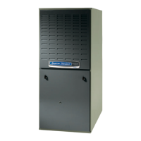
Gas-Fired, Direct Vent Condensing Furnaces
*UXIB040A9241A *UXIC100A9481A
*UXIB060A9361A *UXID100A9601A
*UXIB080A9421A *UXID120A9601A
*UXIC080A9601A
*__First letter may be "A" or "T"
ALL phases of this installation must comply with NATIONAL, STATE AND LOCAL CODES
*DXIB040A9241A
*DXIB060A9361A
*DXIB080A9421A
*DXIC100A9481A
*DXID120A9601A
IMPORTANT -- This Document is customer property and is to remain with this unit.
Please return to service information pack upon completion of work.
*UX-1 *DX-1
A/R
FLOW
UPFLOW
DOWNFLOW
AIR
FLOW
AIR
FLOW
/
UPFLOW/HORIZONTAL
\
DOWN FLOW/HORIZONTAL FLOW
o
A341624P06
Question and Answer IconNeed help?

Do you have a question about the American Standard AUXID100A9601A and is the answer not in the manual?

American Standard AUXID100A9601A Specifications

General IconGeneral
BrandAmerican Standard
ModelAUXID100A9601A
CategoryFurnace
LanguageEnglish

Summary

SAFETY SECTION

CARBON MONOXIDE HAZARD

Critical steps to prevent carbon monoxide poisoning during furnace operation.

FIRE AND EXPLOSION HAZARDS

Warning about potential fire or explosion risks from improper installation or servicing.

GENERAL INSTALLATION INSTRUCTIONS

LOCATION AND CLEARANCES

Specifies required clearances from combustible materials and optimal furnace placement.

FURNACE INSTALLATION CONFIGURATIONS

UPFLOW INSTALLATION GUIDELINES

Instructions for installing the furnace in an upflow position.

AIR FOR COMBUSTION AND VENTILATION

CONFINED SPACE VENTILATION REQUIREMENTS

GENERAL VENTING GUIDELINES

VENTING LENGTH TABLES AND CONFIGURATIONS

TERMINAL CLEARANCES

HORIZONTAL VENTING THROUGH WALL

DOWNWARD VENTING PROCEDURES

CONDENSATE DRAIN INSTRUCTIONS

FIELD WIRING DIAGRAMS

1 STAGE HEATING WIRING DIAGRAM

Wiring diagram for a 1-stage heating furnace with a 1-stage thermostat (no cooling).

1 STAGE HEATING/COOLING WIRING DIAGRAM

Wiring diagram for a 1-stage heating/cooling furnace with a 1-stage thermostat.

ELECTRICAL CONNECTIONS AND TWINNING

TWINNING FURNACES AND GAS PIPING

GAS PIPING INSTALLATION GUIDELINES

Instructions for gas piping installation, including shut-off valves, unions, and pipe joint compound.

GAS PIPING AND INPUT CHECK PROCEDURES

COMBUSTION AND INPUT CHECK

Procedure for checking gas flow rate, input rating, and manifold pressure.

MANIFOLD PRESSURE CHECK

START UP AND ADJUSTMENT PROCEDURES

PRELIMINARY INSPECTIONS

Essential initial checks before starting up the furnace, including power, connections, and venting.

LIGHTING INSTRUCTIONS AND SAFETY

Guidance on burner lighting, safety precautions, and system operation sequence.

CONTROL AND SAFETY SWITCH ADJUSTMENTS

LIMIT SWITCH CHECK OUT

Procedure to test the limit switch's function in preventing overheating.

AIRFLOW ADJUSTMENT

Instructions for adjusting furnace airflow by modifying blower motor speed settings.

ABNORMAL CONDITIONS AND TROUBLESHOOTING

EXCESSIVE COMBUSTION PRESSURE

Troubleshooting excessive pressure, often due to venting issues or blockages.

LOSS OF FLAME

Steps to address flame loss during a heating cycle, including ignition sequence.

INDUCED DRAFT BLOWER AND DRAIN BLOCKAGE

Troubleshooting issues with the induced draft blower, pressure switch, and blocked condensate drains.

LOCKOUT AND LIMIT SHUTDOWN RESET

Procedures for resetting the system after a lockout or burner box limit shutdown.

INTEGRATED FURNACE CONTROL ERROR CODES

ERROR FLASH CODE INTERPRETATION GUIDE

Explanation of various flash codes indicating furnace status, errors, and potential causes.

Related product manuals