EasyManua.ls Logo

American Standard YCC018F-L - User Manual

American Standard YCC018F-L
24 pages
Print Icon
To Next Page IconTo Next Page
Loading...
All phases of this installation must comply with the NATIONAL, STATE & LOCAL CODES. In the absence of local codes, the
installation must conform with National Electric Code -- ANSI/NFPA 70 or "LATEST REVISION."
Since Trane has a policy of continuous product and product data improvement,
it reserves the right to change design and specification without notice.
© 2003 American Standard Inc. All rights reserved
Dwg. No. X664209 P01
INSTALLATION
OPERATION
MAINTENANCE
ALL phases of this installation must comply with
NATIONAL, STATE AND LOCAL CODES
IMPORTANT — This Document is customer property and is to remain with this unit. Please return to service information pack upon completion of work.
Package Convertible
Gas/Electric
1-1/2 - 5 Ton
Model:
YCC018F-L YCC036F-H
YCC024F-L YCC042F-M
YCC030F-L YCC048F-M
YCC030F-M YCC048F-H
YCC036F-L YCC060F-M
YCC036F-M
BAYLIFT002A Lifting Lug Kit
HAZARDOUS VOLTAGE - DISCONNECT POWER BEFORE SERVICING
WARNING:
YCC-IOM-1L
18-EB21D1-11
Library
Product Section
Product
Model
Literature Type
Sequence
Date
File No.
Supercedes
Service Literature
Unitary
Packaged Gas/Electric
YCC
Installation, Operation, Maintenance
1I
November 2003
SV-UN-RT-YCC-IOM-1I 11/03
YCC-IOM-1H
10/03
Question and Answer IconNeed help?

Do you have a question about the American Standard YCC018F-L and is the answer not in the manual?

Summary

Locations and Recommendations

Installation Procedures

Location and Clearances

Selecting a location and ensuring adequate clearances for installation.

Placing and Rigging

Procedures for safely lifting and positioning the unit.

Curb Mounting Installation

Rooftop Unit Installation

Ground Level Unit Installation

Ductwork

Gas Piping Installation

Firing Rate Selection

Electrical Wiring

Electrical Connections and Power

Standards for electrical power supply and connections to the unit.

Start-Up Procedures

Pre-Start Checklist

Essential checks before initiating unit startup.

Operational Startup

Procedures for starting the unit in cooling and heating modes.

Troubleshooting Chart

Maintenance

Overview

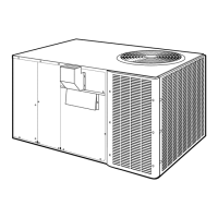
This document outlines the installation, operation, and maintenance procedures for Trane/American Standard Packaged Convertible Gas/Electric units, specifically models YCC018-060F. These units are designed for outdoor mounting with a vertical condenser discharge and can be installed at ground level or on a roof. They are suitable for both residential and commercial applications, with specific warranty terms for each.

Function Description:

The YCC018-060F series units provide both heating and cooling functions. They are gas/electric packaged units, meaning all components for both heating (gas furnace) and cooling (electric air conditioner) are housed within a single outdoor cabinet. The units are shipped configured for natural gas only, but can be converted for propane use. They are designed for either horizontal or downflow airflow applications, with instructions provided for converting between these configurations. The heating cycle is controlled by a solid-state ignition system, and the cooling cycle utilizes a compressor and outdoor/indoor fan motors.

Important Technical Specifications:

  • Models Covered: YCC018F-L, YCC024F-L, YCC030F-L, YCC030F-M, YCC036F-L, YCC036F-H, YCC036F-M, YCC042F-M, YCC048F-M, YCC048F-H, YCC060F-M.
  • Airflow Configurations: Horizontal and Downflow.
  • Fuel Type: Shipped for natural gas; convertible to propane.
  • Refrigerant: Pre-charged with Refrigerant-22.
  • Gas Supply Pressure (Natural Gas): Maximum 13.8 inches Water Column (W.C.), Minimum 5.0 inches W.C.
  • Gas Supply Pressure (Propane): Maximum 13.8 inches W.C., Minimum 11.0 inches W.C.
  • Manifold Pressure (Natural Gas, high input): 3.3 inches W.C.
  • Manifold Pressure (Natural Gas, low input): 3.3 inches W.C.
  • Manifold Pressure (Propane): 10.0 inches W.C.
  • Orifice Sizes (0-2000 ft elevation): Natural Gas (high input) #42, Natural Gas (low input) #44, Propane #54.
  • Orifice Sizes (2000-4500 ft elevation): Natural Gas (high input) #43, Natural Gas (low input) #45, Propane #55.
  • Condensate Drain: 3/4-inch female NPT connection, requires a trap and 1/4" per foot pitch.
  • Electrical: Requires proper grounding and adherence to local/national electrical codes. Thermostat heat anticipator setting: 4 amps.
  • Filter Specifications (Nominal CFM, Filter Sq.Ft.-Size, Filter Resistance):
    • YC-018F/G: 600 CFM, 2.00 sq.ft., 0.05 resistance
    • YC-024F/G: 800 CFM, 2.67 sq.ft., 0.05 resistance
    • YC-030F/G: 1000 CFM, 3.33 sq.ft., 0.05 resistance
    • YC-036F/G: 1200 CFM, 4 sq.ft., 0.05 resistance
    • YC-042F/G: 1400 CFM, 4.67 sq.ft., 0.05 resistance
    • YC-048F/G: 1600 CFM, 5.33 sq.ft., 0.05 resistance
    • YC-060F/G: 2000 CFM, 6.67 sq.ft., 0.05 resistance
  • Thermostat Wire Size and Maximum Length:
    • 18 AWG: 75 ft
    • 16 AWG: 125 ft
    • 14 AWG: 200 ft

Usage Features:

  • Outdoor Installation: Designed for ground level or rooftop mounting.
  • Convertible Airflow: Units can be configured for horizontal or downflow supply and return air. Conversion involves repositioning covers and potentially installing a flue restrictor for low-fire operation.
  • Roof Mounting: Requires a roof mounting curb (BAYCURB030/38A or field fabricated) and spreader bars for hoisting to prevent damage. The unit's drip lip should sit over the outside corner of the curb. Hold-down brackets secure the unit to the curb.
  • Ground Level Mounting: Units are placed on a pad (same size or larger than the unit) and secured with five rubber isolators.
  • Ductwork Connection: Flexible canvas connectors are recommended to minimize noise and vibration. Ductwork outside the structure must be insulated (minimum 2 inches) and weatherproofed.
  • Gas Piping: Requires a tapped shut-off gas cock, a ground union joint, and a drip leg (minimum 6 inches deep) to collect sediment. Gas supply pressure must be checked and regulated if excessive.
  • Electrical Connections: All wiring must comply with national, state, and local codes. A weatherproof disconnect switch is required. The unit must be electrically grounded. Low voltage control wiring should not be run with power wiring unless properly rated.
  • Start-up Procedure: Includes pre-start checklist, voltage check, and specific steps for starting in cooling and heating modes. Compressor crankcase heater must be energized for eight hours before starting the compressor.
  • Heating Cycle Operation: Solid-state ignition control lights burners. Combustion blower energizes, pressure switch closes, gas valve opens, ignitor sparks, and flame detector confirms ignition. Indoor blower motor energizes after a delay.
  • Cooling Cycle Operation: Compressor contactor and indoor fan relay energize, operating the compressor and outdoor/indoor fan motors.
  • Safety Features: Temperature limit switch (TCO) protects against overheating, and a fusible link (FS) protects against flame rollout due to flue blockage. The IGN LED Diagnostic Indicator provides fault codes for troubleshooting.

Maintenance Features:

  • Routine Maintenance (Owner):
    • Filters: Check weekly for the first four weeks in new homes, then regularly. Replace disposable filters; clean permanent filters with mild detergent and water, ensuring they are thoroughly dry before reinstallation. Replace permanent filters annually if washing is ineffective or they show signs of deterioration.
    • Condenser Coil: Clean the coil surface with a soft-bristled brush to remove dust and dirt. Keep vegetation clear from the coil area.
    • General Unit Inspection: Regularly inspect the unit for obvious deterioration.
  • Serviceman Maintenance (Cooling Season - Annually):
    • Check filters, motors and drive system components, economizer gaskets, safety controls, electrical components and wiring (for tightness), condensate drain (for cleaning), unit duct connections, unit mounting support, and overall unit condition.
  • Serviceman Maintenance (Heating Season - Annually):
    • Visually inspect the unit for airflow obstructions to combustion and condenser coil.
    • Inspect control panel wiring for tight connections and intact insulation.
    • Check gas ignition system operation by turning off gas supply to verify valve closure and reignition cycle.
    • Inspect inside of burners and burner ports for deposit buildup and corrosion; clean with a dry cloth or replace if excessive.
  • Flue Cleaning (Serviceman - Annually):
    • Inspect flue for flaking rust and soot deposits.
    • Procedure involves turning off power and gas, removing access panels, combustion blower assembly, flue box, and flue restrictors.
    • Disconnect gas supply line and remove burner-manifold assembly.
    • Remove inlet turbulators carefully.
    • Wipe flue box and baffles clean with a dry cloth.
    • Replace all gaskets and damaged turbulators.
    • Reassemble unit, check wiring, leak test gas connections, and reinstall panels.
    • Visually inspect airflow opening for combustion.
    • Follow start-up procedure to return unit to service.
  • Safety Precaution: Do not operate the unit without the evaporator fan access panel properly installed to prevent severe personal injury or death.

American Standard YCC018F-L Specifications

General IconGeneral
RefrigerantR-410A
Voltage208/230V
Phase1
Frequency60 Hz
Cooling Capacity18000 BTU
StagesSingle
Sound Pressure Level (Outdoor)72 dB

Related product manuals