EasyManua.ls Logo

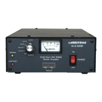
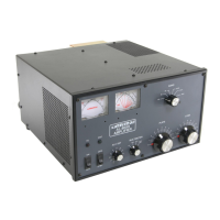
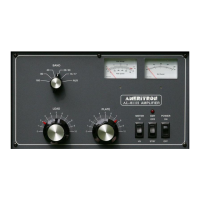
AMERITRON ALS-500M User Manual

AMERITRON ALS-500M
20 pages
To Next Page IconTo Next Page
Page #1 background imageLoading...
Page #1 background image
AMERITRON ALS-500M
INSTRUCTION MANUAL
116 Willow Road
Starkville, MS 39759 USA
662-323-8211
Version 2A
Printed in U.S.A.
500 WATT
SOLID STATE MOBILE AMPLIFIER
PLEASE READ THIS MANUAL BEFORE OPERATING THIS EQUIPMENT !
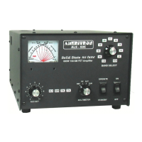
The Ameritron ALS-500M is a 500 watt PEP output solid state linear amplifier using rugged, conservatively rated bipolar RF
devices in the power output section. The ALS-500M operates at full power with continuous frequency coverage from 1.5
through 21.6 MHz. This amplifier requires no tuning adjustments. Broad band 5 pole filter provide output harmonic
suppression in excess of 60 dB for all frequencies above 8 MHz, and more than 70 dB on all TV channels. Export
modifications are available to extend operation to 30 MHz with a copy of a valid amateur license.
The ALS-500M uses two pairs of 2SC2879 transistors operating at 13.8 volts nominal in a push-pull output configuration.
High quality RF components combine with load fault sensing, temperature protection, and one switch frequency selection to
make this one of the simplest and easiest to operate amplifiers today. The ALS-500M operates on 13.8 Vdc electrical systems
and draws a peak current of 80 amperes at full output.
WARNING: THIS AMPLIFIER IS DESIGNED FOR USE IN VEHICLES
WITH NEGATIVE GROUND 12 VOLT ELECTRICAL SYSTEMS ONLY.
The battery should be maintained between 13.8 and 16.5 volts dc.
Question and Answer IconNeed help?

Do you have a question about the AMERITRON ALS-500M and is the answer not in the manual?

AMERITRON ALS-500M Specifications

General IconGeneral
Power Output500 W
Input Impedance50 Ohms
Output Impedance50 Ohms
CoolingFan cooled
Weight25 lbs
Power Supply120/240 VAC
ModesSSB, CW, AM, FM

Summary

ALS-500M Features

Load Fault Protection

Bypasses amplifier if load impedance or bandswitch settings are incorrect.

General Information

Load Fault Circuit

Explains the circuit that bypasses the amplifier due to incorrect settings or reflected power.

SWR Considerations

Covers SWR effects, overload tolerance, and safety limits for reflected power.

Installation

Power Requirements

Details voltage and current requirements for the amplifier's operation.

Fuse Holder Installation

Instructions for installing low and high current fuse holders correctly.

Grounding

Interconnections

Wiring Diagram

Visual representation of amplifier component connections.

Connection Steps

Outlines sequential procedures for establishing all necessary connections.

Operation

Related product manuals