EasyManua.ls Logo

AMERITRON ALS-1300 User Manual

AMERITRON ALS-1300
28 pages
To Next Page IconTo Next Page
Page #1 background imageLoading...
Page #1 background image
1
Ameritron ALS-1300
1200-watt
NO TUNE
TMOS-FET AMPLIFIER
The Ameritron ALS-1300 is a 160 through 15-meter 1200-watt output solid-state amplifier. An optional user-
installed MOD-10MK filter assembly extends operation to 12- and 10-meters. The ALS-1300 uses eight 50-
volt conservatively rated linear RF MOSFETS. These 50-volt linear FET’s produce an exceptionally clean
signal compared to other solid-state amplifiers. Fan speed is regulated by temperature sensors assuring
conservative cooling with minimum noise.
Nominal driving power is 90 watts for 1200-watts output (approximately 11 dB gain) on most bands. The
compact 10.5” wide by 6.75” high amplifier package (depth only 19”) fits nearly any station configuration. The
attractive desk-top amplifier unit weighs only 22 pounds.
An external 50-volt 50-ampere regulated switching power supply powers the ALS-1300. The supply is wired
for 240 VAC (200-260 VAC, 50-60 Hz, 15 amperes), but can be rewired for 120 VAC operation for lighter duty
operation.
Question and Answer IconNeed help?

Do you have a question about the AMERITRON ALS-1300 and is the answer not in the manual?

AMERITRON ALS-1300 Specifications

General IconGeneral
Impedance50 Ohms
CoolingForced Air
Tube Complement4 x 3-500Z
ALCYes
Power Output1000W CW
Power Requirements220-240 VAC
Gain13 dB

Summary

Power Supply

Power Line Requirements

Specifies voltage, current, and fuse requirements for the power input.

General Information

Amplifier Overview

Provides an overview of the ALS-1300, including power, frequency range, and transistors.

Installation

Airflow Requirements

Details airflow requirements, inlet/outlet locations, and temperature considerations for cooling.

Installation Safety and Setup

Operational Warnings

Critical warnings about blocking airflow, water exposure, and power cord connections.

Fuse Installation Procedures

Emphasizes using correct voltage/current rated fuses and proper installation steps.

Interconnection Wiring

Wiring Diagram

Illustrates the overall interconnection diagram for the amplifier, transceiver, and power supply.

Amplifier Rear Panel

Rear Panel Connections

Details the purpose and connection of each port on the amplifier's rear panel.

Front Panel Overview

Front Panel Controls and Indicators

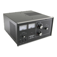
Identifies and illustrates the various controls and indicators on the front panel.

Front Panel Operation

Meter and LED Functions

Explains the dual-movement meters, LEDs for status, and multimeter functions.

Initial Setup and Testing

Initial Checkout Procedure

Step-by-step guide for verifying connections and powering up the amplifier for the first time.

First Use Verification

Power-Up and Band Check

Details initial testing steps, including power-up sequence, voltage checks, and band selection.

Technical and Operational Overview

PA Module Functionality

Details the power amplification stages using PAM-600 modules and FETs.

Related product manuals