8
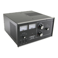
Amplifier Rear Panel
PWR SUPPLY To prevent connecting the power plug wrong, the large black multi-pin connector is
indexed by an offset in the two round pins. One round index hole is closer to the outer connector edge. Mate
the round pins and holes and seat the male plug fully onto the amplifier rear panel pins.
ALC Optional connection. Connects to radio ALC input. Mandatory if using a radio over 100 watts.
RLY Connect to radio amplifier keying line. Radio must pull this line below 2 volts to transmit.
GND Connect to station ground buss. This connection is for safety.
IN Connect through good 50-ohm coaxial cable to radio’s antenna output connector. This can be a smaller
cable like RG-58/U.
OUT To 50-ohm antenna, antenna tuner, power meter. This is the high power output. 50-ohm coaxial cable must
safely handle 1200-watts.
REMOTE Interfaces for optional ARI-500 Amplifier Radio Interface.
1.) Connect the station electrical safety ground to the rear panel wing nuts. National safety codes require the
station ground to be bonded to the power mains safety ground at the building entrance.
2.) Connect the power supply to the amplifier.
3.) Connect the RLY line to the transceiver’s accessory RELAY or XMT port. This port must pull low for
transmit, and be open circuit when receiving. Relay control voltage from the ALS-1300 is 12 volts
positive with only 15 mA current. You should always check your transceiver’s manual, but almost any
standard transceiver directly interfaces to this amplifier.
4.) Connect the OUT (output) port to the appropriate point in your station. This is the high power RF output
cable. This connection would go to your 1500-watt rated Power/SWR meter, antenna, or antenna
matching device. Good quality Mini-8 or RG-8X cables are acceptable for anything but RTTY use,
although larger RG-8 style cables are normally preferred. Your antenna matching system must connect
to this port.
5.) Connect the IN connector to your transceiver. Do not install any active antenna matching devices on this
port. In general short and direct cable connections are best, although high quality cables can be very
long without adversely effecting performance. RG-58/U or Mini-8 (RG-8X) style cables are acceptable.
You should never use a tuner of any type on the amplifier input, nor should you drive this amplifier
with over 100 watts peak envelope power. Never use a non-FCC accepted device with this amplifier.
6.) The ALC line is optional, but recommended. Without ALC you must monitor your drive power so that
you don’t overdrive the amplifier which will cause intermodulation distortion. The ALS-1300 ALC
circuit monitors the RF output power and reflected power.
7.) Operate the bandswitch manually during initial testing. Do not connect band decoders or computer
interfaces until initial tests are completed.